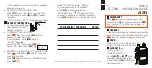
2. Refrigeration lines in cases in line-ups can be reduced. However, the lines should be no
smaller than the main trunk lines in at least 1/3 of the cases and no smaller than one size
above the case lines to the last case. Reductions should not exceed one line size per case. It
is preferred to bring the main trunk lines in at the center of line-up. Liquid lines on systems
on hot gas defrost must be increased one line size above the main trunk line for the entire
line-up. Individual feed lines should be at the bottom of the liquid header. (See proper
liquid line piping diagram.)
3. Do not run refrigeration lines from one system through cases on another system.
4. Use dry nitrogen in lines during brazing to prevent scaling and oxidation.
5. Insulate suction lines from the cases to the compressor with 3/4" wall thickness foam on
low temperature cases to provide maximum of 65-degree super heated gas back to the
compressor and prevent condensation in exposed areas. Insulate suction lines on medium
temperature cases with 1/2" thick insulation in exposed areas to prevent condensate
droppage.
6. Suction and liquid lines should never be taped or soldered together. Adequate heat
exchanger is provided in the case. Kysor//Warren recommends use of heat exchanger in all
medium and low temperature case that are not mechanically sub-cooled for proper
operation.
7. Refrigeration lines should never be placed in the ground unless they are protected against
moisture and electrolysis attack.
8. Always slope suction lines down toward the compressor, 2" each 10’. Do not leave dips in
the line that would trap oil.
9. Provide P traps at the bottom of suction line risers, 4’ or longer. Use a double P trap for
each 20’ of risers. P traps should be the same size as the horizontal line. Consult the
technical manual or legend sheet for proper size risers.
10. Use long radius ells and avoid 45 degree ells.
11. Provide expansion loops in suction lines on systems on hot gas defrost. An expansion loop
is required for each 100’ of straight run.
12. Strap and support tubing to prevent excessive line vibration and noise.
13. Brazing of copper to copper should be with a minimum of 10% silver. Copper to brass or
copper to steel should be with 45% silver.
UNIT INSTALLATION
45
Summary of Contents for 6RLG3
Page 3: ...2 6 2006 2 Addendum Ballast Relocation 2 ...
Page 5: ...2 6 2006 4 Addendum Ballast Relocation Wiring Diagram Both Canopy and Raceway 4 ...
Page 6: ...2 6 2006 5 Addendum Ballast Relocation Wiring Diagram for Canopy Light 5 ...
Page 9: ...Plan Views and Cross Sections D6L D6 D6H 8 ...
Page 10: ...D6RL D6R 9 ...
Page 11: ...QD6 10 ...
Page 34: ...D6 Electrical Model Table QD6 1 3 04 Through D6H 1 3 6 UNIT INSTALLATION 33 ...
Page 35: ...D6 Electrical Model Table D6H 1 3 6 Through D6R 1 3 4 UNIT INSTALLATION 34 ...
Page 36: ...D6 Electrical Model Table D6R 1 3 4 Through D6RL G 1 6 UNIT INSTALLATION 35 ...
Page 39: ...Wiring Diagram UNIT INSTALLATION 38 ...
Page 40: ...Wiring Diagram Canopy One 1 and Two 2 Light Rows UNIT INSTALLATION 39 ...
Page 41: ...Wiring Diagram Canopy Two 2 and Three 3 Light Rows UNIT INSTALLATION 40 ...
Page 42: ...Wiring Diagram Canopy Two 2 Light Rows and Nose Light UNIT INSTALLATION 41 ...
Page 43: ...Wiring Diagram Off Cycle Defrost UNIT INSTALLATION 42 ...