Troubleshooting
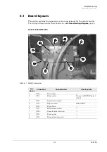
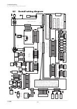
Board layouts
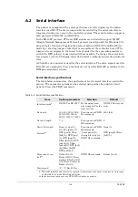
FS-6700
Scanner interface board KP-622
Connect board connector/KP-616
The two connectors at the right side of the printer are mounted on the connect
board. These connectors derive engine signals. For pin assignments, refer to
Table 6. 2 CN13 (Scanner CN1) pin assignment
Pin No.
Signal
1
+5V
2
GND
3
LONB
4
LASER
5
VDOUT+
6
VDOUT-
7
PD
8
SCCLK
9
SCRDY*
10
SCANNER*
11
GND
12
+12V
Summary of Contents for Ecosys FS-6700
Page 1: ...Service Manual L A S E R P R I N T E R Ecosys FS 6700 ...
Page 6: ...Conventions Preface vi This page left intentionally blank ...
Page 11: ...B 5 FS 6700 ...
Page 61: ...Troubleshooting Print quality problems 6 42 FS 6700 This page left blank intentionally ...
Page 83: ...Disassembly Disassembly Option paper feeder 5 22 FS 6700 This page left blank intentionally ...
Page 114: ...2SHUDWLRQ WKHRU QJLQH FRQWUROOHU V VWHP éðêì 609 33 LJXUH 7149 3RZHU VXSSO FLUFXLW GLDJUDP ...
Page 122: ...2SHUDWLRQ WKHRU RJLF FRQWUROOHU V VWHP éðêä 609 33 QJLQH LQWHUIDFH EORFN GLDJUDP ...
Page 123: ...2SHUDWLRQ WKHRU RJLF FRQWUROOHU V VWHP éðéí 609 33 7KLVýSDJHýOHIWýEODQNýLQWHQWLRQDOO ...

