5
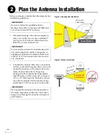
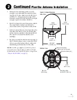
• Make sure the mounting surface is wide
enough to accommodate the antenna’s base
(see Figure 5). Also make sure it is flat, level
(within ±1°), strong enough to support the
antenna’s weight (198 lbs (89.8 kg)) and rigid
enough to prevent antenna vibration.
• Be sure to preserve enough free space outside
the access hatch to allow a technician to
remove the hatch and perform maintenance.
• Select a location that is not too high above the
waterline (less than 1/2 the vessel’s length),
and as close as possible to the intersection of
the vessel’s fore-and-aft centerline and
midships.
• Be sure to mount the antenna near enough to
the TV-Hub to allow you to connect the 100 ft
(30 m) coax cable between them, while still
maintaining sufficient slack in the cable.
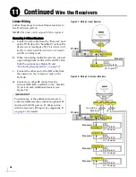
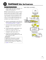
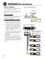
NOTE:
For RF1, you
must
use an RG-11 cable. If
you need to use a longer cable, use a RG-11 (75
)
cable that does not exceed 200 ft (60 m) in length (see
“Prepare the RF Cables” on page 9
).
13V/22KHz
18V/22KHz
Power/Data
13V
18V
57.28"
(145.50 cm)
19.01"
(48.29 cm)
Ø48.80"
(123.00 cm)
Side View
Cable
Connectors
9.74"
(24.74 cm)
Mounting Hole
4x Ø.63" (1.59 cm)
Ø13.78"
(35.00 cm)
Cable Connectors
(cable cover not shown)
Service Hatch (x2)
Bottom View
RF4
RF3
RF2
RF1
Figure 5: Antenna Dimensions
Continued
Plan the Antenna Installation
2
Summary of Contents for TracVision TV10
Page 1: ...TracVision TV10 Installation Guide ...
Page 53: ......


