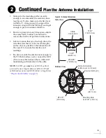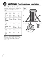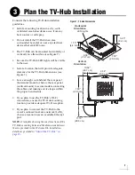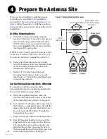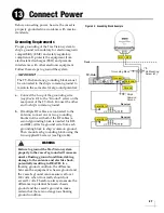
12
j.
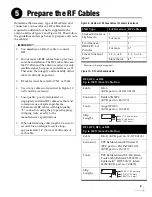
Make sure the RF cable is hand-tightened all
the way into the connector. Then tighten it
with a 7/16" torque wrench to 20 in-lbs, or a
7/16" wrench for 1/4 turn.
k.
Wipe off any excess grease from the outside
of the connector.
l.
Repeat steps
h-k
to connect any additional RF
cables to the antenna’s RF2, RF3, and RF4
connectors. Later, you will connect RF1 to the
TV-Hub and any other RF cable(s) to a
grounding block and receiver(s).
m.
Seal the RF cable connections with silicone
sealant or equivalent.
n.
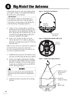
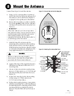
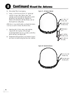
Using a #1 Phillips screwdriver, reinstall the
cable cover to the antenna and secure it in
place with the six #6-32 captive screws and
o.
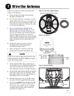
Secure the cables near the antenna connectors
to relieve stress (such as the example in
Figure 18). The cable cover is designed for
aesthetics only – it does not provide any
support for the cables and may become
damaged if cables are not properly strain-
relieved.
p.
Weatherproof and seal the cable access hole
as required.
Figure 17: Cable Cover/Screws/Washers
1
3
V/22KHz
18V/22KHz
Power/D
a
t
a
1
3
V
18V
L
a
bel
L
a
bel
L
a
bel
L
a
bel
L
a
bel
#6-
3
2 C
a
ptive Screw
a
nd W
a
sher (x6)
C
a
ble
Cover
Figure 18: Strain-relief/Service Loops Example
Service Loops
Deck
Through-deck
Protection
Gooseneck
To Belowdecks Equipment
Welded or Bolted to
Ship’s Steel Structure
Strain Relief
Continued
Wire the Antenna
7
Summary of Contents for TracVision TV10
Page 1: ...TracVision TV10 Installation Guide ...
Page 53: ......


