


Step 2
Remove the two faston plugs from the Potentiometer cover and the 5 screws
which secure the cover on the motor housing. (Image 3)
Image 3
Step 3
Remove the gear from the potentiometer axle with a wide flat screwdriver
(Image 3). Then carefully remove the nut under the potentiometer. Desolder
the 3 wires. Observe the position of the three coloured wires. (Image 4)
Image 4
Step 4
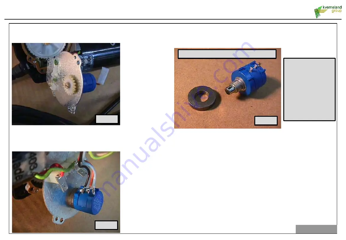
It is now possible to replace the potentiometer. When installing the new
potentiometer place the metal ring under the potentiometer (Image 5). Fix the nut,
and then place the potentiometer gear back on the potentiometer axle (Image 3).
Image 5
Step 5
Place the lid back on the motor using the five screws. Note the paper gasket on
top of the electric motor.
Solder the wires back on the potentiometer again in the right color combination and
connect the two faston connectors from the motor again.
Step 6
Replace the top cover and do a functional test to check if the potentiometer is
working properly. Test the resistance of the actuator (0Ω in 1000Ω out)
Note: do not use pincers on the potentiometer!
Note:
It does not make a
difference how the
sprocket of the
potential meter is
fitted. Due to the
construction inside the
right position will be
found automatically
after 1 time opening
and closing.
2. Sensors and actuators
30
Step 7
After repair/ changing the actuator, the actuator must be calibrated. Calibration of
this actuators can be done in the screen “Hopper&Act Calibration” (see §4.1).
Summary of Contents for EDW2
Page 3: ...1 System overview 3 ...
Page 9: ...1 1 5 1 Battery cable 9 1 System overview ...
Page 10: ...Relay connections Not available on spare parts 1 1 5 1 Battery cable 10 1 System overview ...
Page 11: ...2 1 5 2 IM Tellus connection cable 11 1 System overview ...
Page 12: ...1 5 3 ISOBUS connector 3 12 3 5 2 1 6 4 7 8 9 1 System overview ...
Page 13: ...1 6 Communication and power cables Machine side 13 1 System overview ...
Page 32: ...3 1 Machine Software overview EDW ISO II 1 19 3 Software screens 32 ...