1
Control cabinet (continued)
7 of 70
Hardware R2.2.8 11.98.02 en
G
Standard PC Hardware
With its powerful Pentium processor and main memory, the standard PC hardware forms the
basis of the processor unit. The standard PC also includes a hard disk for storing the entire
control software, including online help and online documentation, a floppy disk drive for
archiving purposes and a CD--ROM drive for reading the CD--ROM supplied in the cabinet.
The CD--ROM contains the operating system, Windows, the control software including the
relevant technological process, the online help and the complete documentation for the con-
trol cabinet and the robot.
G
Multi--function card
The multi--function card incorporates the system and user I/Os and an Ethernet controller,
and forms the interface between the KCP and the PC. The card is designed as a PC plug--in
card and accommodates up to two DSEAT modules.
G
Digital servo--electronics (DSEAT)
The DSEAT module fitted on the multi--function card with its own DSP (digital signal proces-
sor) is responsible for control of a servo power module with phase current command values
and parameterization data, processing of the error and situation information read by the
servo power module and communication with the module for R/D conversion.
G
Resolver/digital converter (RDC)
Installed on the robot base, the R/D converter with its own DSP (digital signal processor)
performs the functions of resolver power supply, R/D conversion, open--circuit monitoring of
the resolvers and monitoring of the motor temperature. This converter communicates with
the DSEAT via a serial interface.
1.2.2
Power unit
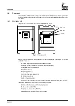
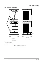
The power unit comprises the areas highlighted in Fig. 2 and Fig. 3.
G
Power infeed with mains filter, main switch with fuse and m.c.b.
G
Basic modules and servo power modules
G
Safety module (on processor unit)
G
Back--up battery for control hardware
For data protection, the computer is supplied with power by a battery for a maximum of 10x1
minute in the event of power failure.
G
Transformer (optional)
G
Fans for cooling the cabinet
Summary of Contents for KR C1
Page 1: ...Hardware R2 2 8 11 98 02 en 1 of 70 SOFTWARE KR C1 Hardware Release 2 2...
Page 30: ...Hardware 30 of 70 Hardware R2 2 8 11 98 02 en Fig 13 Circuit diagram X931 X604...
Page 32: ...Hardware 32 of 70 Hardware R2 2 8 11 98 02 en Fig 15 Inputs...
Page 34: ...Hardware 34 of 70 Hardware R2 2 8 11 98 02 en...
Page 35: ...35 of 70 Hardware R2 2 8 11 98 02 en...


