7
Resolver--to--Digital Converter (RDC)
61 of 70
Hardware R2.2.8 11.98.02 en
7
Resolver--to--Digital Converter (RDC)
7.1
Description of the RDC
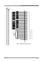
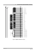
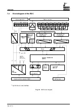
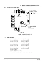
The RDC card with built--in DSP (Digital Signal Processor) is located in a housing at the base
of the robot and performs the following functions:
--
Generation of all necessary operating voltages from the 27V supply;
--
Resolver power supply for 8 axes;
--
Isolated power supply of 8 temperature sensors (KTY 84) in the motor windings;
--
R/D conversion for up to 8 axes (approx. 3 x 4096 increments/motor revolution)
--
A/D conversion for 8 temperature sensors (12--bit resolution);
--
Evaluation of 2 EMT channels (1 EMT);
--
Resolver open--circuit monitoring;
--
Motor temperature monitoring;
--
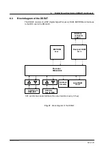
Communication with the DSEAT via an RS422 serial interface.
The RDC also has an EEPROM that stores the following data even after the controller is swit-
ched off:
--
Operating hour counter (counts in minutes when the brakes are opened; can be
displayed with $ROBRUNTIME);
--
Absolute position (important for maintaining the mastering), in increments;
--
Resolver position (this value is compared to the actual resolver position on power--
up -- tolerance 6 increments), in increments;
--
Calibration data (offset, symmetry).
Moreover, this EEPROM also contains a write--protected area with the boot program for the
processor.
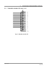
The cable cores of the 6 robot axes are routed into the housing via a special molding and
are plugged directly to the circuit board.
The cables of the 2 external axes are passed through a screwed gland and connected to the
RDC.
Advantages of this independent module:
--
The DSEAT can be smaller and can therefore be designed as a PC module;
--
No functions requiring a +/--12V supply voltage are located on the DSEAT: this
configuration would cause problems, because the PC power supply unit cannot
supply the necessary voltage, especially in the case of --12V;
--
The cables for the resolvers and motor temperature do not have to be routed to
the DSEAT:
shorter shielded cables (only in the robot),
no problems of space requirement, stability and cable routing on the DSEAT;
--
The encoder cable contains 6 conductor pairs instead of 20 in the old system:
thinner, more flexible and cheaper cable,
instead of a Harting connector, another (smaller, cheaper) connector can be used.
Summary of Contents for KR C1
Page 1: ...Hardware R2 2 8 11 98 02 en 1 of 70 SOFTWARE KR C1 Hardware Release 2 2...
Page 30: ...Hardware 30 of 70 Hardware R2 2 8 11 98 02 en Fig 13 Circuit diagram X931 X604...
Page 32: ...Hardware 32 of 70 Hardware R2 2 8 11 98 02 en Fig 15 Inputs...
Page 34: ...Hardware 34 of 70 Hardware R2 2 8 11 98 02 en...
Page 35: ...35 of 70 Hardware R2 2 8 11 98 02 en...

