Hardware
68 of 70
Hardware R2.2.8 11.98.02 en
--
The 10th word (value) is the motor temperature of axes 1--8, requested by the DSE
in the command. Normally, this value should vary.
--
The 11th word (error) shows the error bits and EMT signals. Bits 0 to 7 are the error
bits of axes 1 to 8. If a bit is ”high”, an encoder error has been recorded for the axis.
In the component test stand (6 axes), this value is normally set to ”00C0” (hex),
corresponding to ”0000 0000 1100 0000” (binary). This value recognizably repre-
sents the error bits of axis 7 and axis 8 (because these axes are not connected).
Bits 8 and 9 are the EMT signals (see ”EMT mastering”).
--
The 12th word (Chksum) is the checksum for all the data. Normally, this value
should vary.
--
The ”Communication error status” indicates whether more than 3 consecutive
transmissions have failed. If so, the status value is 1. Under normal conditions,
this value is ”0000”. If the status is 1, DSEAT--RDC communication is disrupted
by fault condition(s).
--
The ”Communication error counter” counts all faulty transmissions; under normal
conditions, this value too should be ”0000”.
7.7.2.3 Simulating EMT mastering
G
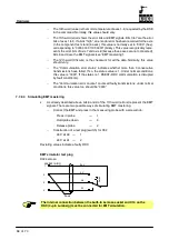
As already described above, bits 8 and 9 of the 11th word (errors) represent the EMT
signals. There are two possible ways of simulating EMT mastering:
--
Connect the EMT and press in the measuring probe with a screw knob:
Press in probe
1
Hold probe down
3
Release probe
2
--
Construction of a test plug (switch) for X32
24 V at A0
1
24 V at A1
2
Deviating values indicate a faulty RDC.
EMT simulator test plug
24 V
0 V
A0
A1
Shield
Sw
itc
h
X32 Lemosa
socket / plug
1
4
3
2
The internal connection between the built--in Lemosa socket and X10 on the
RDC (4--pin Lumberg) must be connected for EMT simulation.
Summary of Contents for KR C1
Page 1: ...Hardware R2 2 8 11 98 02 en 1 of 70 SOFTWARE KR C1 Hardware Release 2 2...
Page 30: ...Hardware 30 of 70 Hardware R2 2 8 11 98 02 en Fig 13 Circuit diagram X931 X604...
Page 32: ...Hardware 32 of 70 Hardware R2 2 8 11 98 02 en Fig 15 Inputs...
Page 34: ...Hardware 34 of 70 Hardware R2 2 8 11 98 02 en...
Page 35: ...35 of 70 Hardware R2 2 8 11 98 02 en...


