background image

Hardware

42 of 70

Hardware R2.2.8 11.98.02 en

5.5

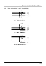
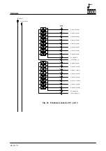
Motor connector X20, axes 1 to 6

a1

X20

a4

a6

a3

a5

Brake A1 26V

Brake A1 0V

Motor A1 W

Motor A1 V

Motor A1 U

b1

b4

b6

b3

b5

Brake A1--6 26V

Brake A1--6 0V

Motor A2 W

Motor A2 V

Motor A2 U

c1

c4

c6

c3

c5

Brake A1--6 26V

Brake A1--6 0V

Motor A3 W

Motor A3 V

Motor A3 U

d1

d4

d4

Motor A4 W

Motor A4 V

Motor A4 U

e1

e4

e6

Motor A5 W

Motor A5 V

Motor A5 U

f1

f4

f6

Motor A6 W

Motor A6 V

Motor A6 U

PE

Ground conductor 2.5 mm2

PE

Ground conductor 6.0 mm2

Fig. 20 Motor connector X20

Summary of Contents for KR C1

Page 1: ...Hardware R2 2 8 11 98 02 en 1 of 70 SOFTWARE KR C1 Hardware Release 2 2...

Page 2: ...to these functions however in the case of a replacement or service work We have checked the content of this documentation for conformity with the hardware and software described Nevertheless discrepa...

Page 3: ...axis power module PM2 600 25 16 15 2 5 Individual axis power module PM1 600 25 16 2 6 Individual axis power module PM1 600 16 16 2 7 Connection diagram for PM 0 PM2 without PM6 600 17 2 7 1 Jumpering...

Page 4: ...f the DSEAT 57 6 4 DSEAT functions 58 6 5 Configuration of the DSEAT 59 6 6 Replacing the DSEAT card 59 6 7 Function test of the DSEAT card 60 6 7 1 Visual inspection of the LEDs 60 6 7 2 Function tes...

Page 5: ...till live even when the main switch is turned off Particularly important maintenance and repair work may be performed only by trained personnel aware of the hazards involved 1 1 1 Cleaning Do not use...

Page 6: ...omponents the processor unit performs all the functions of the control hardware These are Windows user interface with visual display and input Program creation correction archiving and maintenance Dia...

Page 7: ...EAT The DSEAT module fitted on the multi function card with its own DSP digital signal proces sor is responsible for control of a servo power module with phase current command values and parameterizat...

Page 8: ...G1 N1 N2 T1 E2 Q1 F7 Cabinet viewed from front Doors closed Cabinet viewed from rear Rear panels removed Ballast resistors with ventilation Covering removed Fan Temperature sensor Ballast resistor Ex...

Page 9: ...FE201 Servo power module Internal fan Basic cabinet Q1 A1 PM0 600 PM1 600 25 PM1 600 25 16 PM1 600 25 16 Internal fan Top mounted cabinet Servo power module Basic module Main switch with swing frame...

Page 10: ...upply modules are cooled directly by ambient air The controller is designed for an ambient temperature of max 45 C with a heat exchanger or max 55 C with an air conditioner Upstream installation of fi...

Page 11: ...of 70 Hardware R2 2 8 11 98 02 en 1 2 3 Cooling by heat exchanger 1 2 3 Front view Heat flow Inner circuit Rear view Heat flow Outer circuit 1 Heat exchanger 2 Fan inner circuit 3 Fan outer circuit F...

Page 12: ...ons see LEERER MERKER LEERER MERKER 1 6 Replacing the basic and power modules Disconnect the mains cable before removal work is started and take measures to prevent it from being reconnected Voltages...

Page 13: ...are designed for use as external axes or for special applica tions The structure and internal parts are comparable with those of the six axis power mo dule PM6 600 Axis independent and axis specific f...

Page 14: ...ssion elements Interface with safety module FE201 G Logic module incl Bidirectional interface for parallel data transmission from to DSEAT with parity check Current controller and pulse width modulati...

Page 15: ...tch off Control voltage and driver supply power module DSEAT Int circuit voltage Control signals power module N1 N11 Fig 5 PM 0 600 Front view Mains connection 3x400V AC 2 4 2 axis power module PM2 60...

Page 16: ...voltage and driver supply Brake output S3 S2 S1 Hook switches for activating the individual axis switch off Fig 6 PM 2 600 25 16 Front view 2 6 Individual axis power module PM1 600 16 X302M X302L X31...

Page 17: ...S3 S2 X301H1 X301H2 X301M X301L X302M X302L X315 X316 X504 X508 X509 X505 SWITCH 1 SWITCH 2 BRAKE 2 BRAKE1 1Iw 2Iu 1Iu 2Iw 5V Imax PM2 600 25 16 LED Monitor X507 Motor 2 size B and C0 Motor 2 size C...

Page 18: ...64 A Plug position M Imax RMS 32 A Plug position L Imax RMS 16 A The controller detects the connector position and signals an incorrectly connected motor cable With plug position H both cables must a...

Page 19: ...e lettering Betrieb Programmierung Put the jumper in the position Programmierung 2 With the KCP on the BOF GUI call up the menu option HELP VERSION Check if the displayed robot type correspnds with th...

Page 20: ...uit capacitor Ballast resistor ext Rectifier Brake switch Power unit K2 K1 Holding brake SM Overcurrent 3 3 Reset K1 27 V ext Battery ext actual I Kx Kx axis switch off Kx Fig 9 Basic and servo power...

Page 21: ...EMERGENCY STOP delay Dual channel user safeguard operator safety and enabling circuit Operating mode switchover Test Automatic Drives ON circuit 3 1 1 Settings To ensure the safe functioning of the r...

Page 22: ...30 R39 V29 R31 V27 X8 X7 X925 R29 F11 X9 V34 V35 F4 R40 1 X924 R41 V38 C4 V37 X926 2 K3 K4 K5 K6 K8 K7 K13 K14 K1 K2 K9 X927 V39 Fig 10 FE201 version A Drives ON relay with LED Connector interface Vol...

Page 23: ...closed Pos b EMERGENCY STOP without path oriented braking Pos a EMERGENCY STOP with path oriented braking X7 X9 X1 X6 X10 Drives ON relay with LED Voltage supply connector DIP FIX switch X10 DIP FIX...

Page 24: ...8 X921 7 X11 21 X11 22 X921 10 K2 K2 Emergency Stop 2 K1 K4 MFC X923 23 X807 23 Emergency Stop channel 2 V22 X923 9 X807 9 X806 12 X19M1 9 X806 7 X806 11 X807 10 X923 10 X921 12 X11 5 X11 6 X921 15 T...

Page 25: ...ves ON K9 X922 7 X10⁵ 7 K1 19 19 21 21 17 17 19 19 T1 T2 K2 PMx 600 A7 12 PMx 600 A7 12 X922 20 X105 20 PC PM ready FE201 X925 16 X105 16 Drives ready X105 18 X925 18 17 17 19 19 X925 7 X10⁵ 7 K1 T1 T...

Page 26: ...T1 X19M1 5 X806 8 X807 13 X923 13 K8 K7 T2 Auto Extern K3 K7 Test mode group K7 K8 K8 MFC V27 X923 28 X807 28 TEST mode X19M1 4 X806 7 X807 14 X923 14 K4 K3 K7 K3 Automatic mode group K3 K4 K4 MFC V3...

Page 27: ...for switch off the external axis must be positioned in the active program the servo enable must be inhibited and the brake applied The axis may not be moved in the program for the duration of the axi...

Page 28: ...r the driver stages of all external axes which temporarily drops to zero due to the current surge of an axis being switched on This error only takes place when the individual axis switch off is activa...

Page 29: ...4 Individual axis switch off for external axes continued 29 of 70 Hardware R2 2 8 11 98 02 en Fig 12 Wiring diagram switch off for external axes...

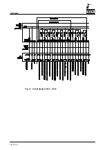
Page 30: ...Hardware 30 of 70 Hardware R2 2 8 11 98 02 en Fig 13 Circuit diagram X931 X604...

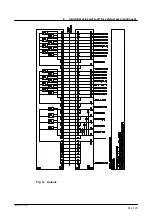
Page 31: ...4 Individual axis switch off for external axes continued 31 of 70 Hardware R2 2 8 11 98 02 en Fig 14 Outputs...

Page 32: ...Hardware 32 of 70 Hardware R2 2 8 11 98 02 en Fig 15 Inputs...

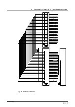
Page 33: ...4 Individual axis switch off for external axes continued 33 of 70 Hardware R2 2 8 11 98 02 en Fig 16 Cross connections...

Page 34: ...Hardware 34 of 70 Hardware R2 2 8 11 98 02 en...

Page 35: ...35 of 70 Hardware R2 2 8 11 98 02 en...

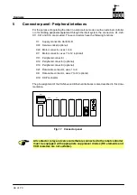
Page 36: ...Motor connector axes 1 to 6 X7 Motor connector axes 7 to 12 optional X11 Peripheral connector X12 Peripheral connector optional X13 Peripheral connector optional X21 Data cable connector axes 1 to 8...

Page 37: ...th one another is not permitted Emergency Stop relay 0V 40 0 V connection of the Emergency Stop relays for connection to the internal or external supply voltage Ext enabling channels 1 and 2 5 6 23 24...

Page 38: ...ct is closed if Automatic or External is selected Rapid gauging channels 1 to 4 13 14 31 32 49 Inputs are read by the DSEAT at the 125 s clock rate When a 0 1 or 1 0 edge is detected the actual axis v...

Page 39: ...p relay channel 1 Em Stop relay channel 2 Em Stop relay 0V Emergency Stop circuit for a robot without periphery X11 37 1 19 2 3 20 21 4 22 40 0V internal 24V internal Em Stop channel 1 I Em Stop chann...

Page 40: ...t for a robot with periphery X11 Em Stop button periphery Em Stop switching device Em Stop periphery 37 1 19 2 3 20 21 4 22 40 0V internal 24V internal Em Stop channel 1 I Em Stop channel 1 O Em Stop...

Page 41: ...Hz 25A only with transformer 3x440V 50 60Hz 25A 3x480V 50 60Hz 25A 3x500V 50 60Hz 25A 3x550V 50 60Hz 25A X1 L1 N PE Service socket Standard version with PEN conductor in the mains Supply voltage depen...

Page 42: ...b4 b6 b3 b5 Brake A1 6 26V Brake A1 6 0V Motor A2 W Motor A2 V Motor A2 U c1 c4 c6 c3 c5 Brake A1 6 26V Brake A1 6 0V Motor A3 W Motor A3 V Motor A3 U d1 d4 d4 Motor A4 W Motor A4 V Motor A4 U e1 e4...

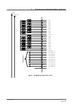
Page 43: ...al 1 X7 1 2 6 4 5 Brake A7 26V Brake A7 0V Motor A7 W Motor A7 V Motor A7 U Housing 1 X7 2 2 6 4 5 Brake A8 26V Brake A8 0V Motor A8 W Motor A8 V Motor A8 U Housing 1 X7 3 2 6 4 5 Brake A9 26V Brake A...

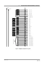
Page 44: ...TOP relay channel 2 40 EM STOP relay 0V 8 Safeguard channel 1 O 25 Safeguard channel 2 I 26 Safeguard channel 2 O 41 Ext drives OFF I 42 Ext drives OFF O 43 Ext drives ON I 44 Ext drives ON O 9 EM STO...

Page 45: ...apid gauging channel 4 15 Cross connection 1 16 Cross connection 2 17 Cross connection 3 18 Cross connection 4 33 Cross connection 5 34 Cross connection 6 35 Cross connection 7 36 Cross connection 8 5...

Page 46: ...100mA 76 Output 3 100mA 94 Output 4 100mA 59 Output 5 100mA 77 Output 6 100mA 95 Output 7 100mA 60 Output 8 100mA 78 24V output 9 16 79 Output 10 100mA 96 0V output 9 16 61 Output 9 100mA 97 Output 11...

Page 47: ...onnection 16 90 Cross connection 17 106 Cross connection 18 107 Cross connection 19 108 Cross connection 20 105 n c Cross connection to optional connector X12 99 0V input 1 8 82 Input 2 64 Input 1 100...

Page 48: ...100mA 98 Output 14 100mA 63 Output 15 100mA 81 Output 16 100mA 15 Cross connection 1 16 Cross connection 2 17 Cross connection 3 18 Cross connection 4 33 Cross connection 5 34 Cross connection 6 35 C...

Page 49: ...Cross connection 18 107 Cross connection 19 108 Cross connection 20 Cross connections to X11 99 0V input 1 8 82 Input 2 64 Input 1 100 Input 3 65 Input 4 101 Input 6 84 Input 8 83 Input 5 66 Input 7...

Page 50: ...controller 4 not assigned 5 not assigned 6 not assigned 7 CAN high signal of first controller 8 not assigned 9 not assigned Fig 30 CAN bus Sub D connector X801 5 10 Ethernet Sub D connector X802 1 GND...

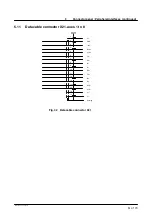
Page 51: ...ontinued 51 of 70 Hardware R2 2 8 11 98 02 en 5 11 Data cable connector X21 axes 1 to 8 1 n c X21 2 GND 3 24V 4 CLKo 5 CLKo 6 FSi 7 FSi 8 Di 9 Di 10 FSo 11 FSo 12 Do 13 Do 14 CLKi 15 CLKi 17 n c 16 n...

Page 52: ...re R2 2 8 11 98 02 en 5 12 Data cable connector X8 axes 7 to 12 optional 1 n c X8 2 GND 3 24V 4 CLKo 5 CLKo 6 FSi 7 FSi 8 Di 9 Di 10 FSo 11 FSo 12 Do 13 Do 14 CLKi 15 CLKi 17 n c 16 n c Housing Fig 33...

Page 53: ...Display screen KCP 4 CAN bus 2 CAN bus 4 RxD 1 TxD 3 TxD 2 RxD 9 Enabling GND 3 EM STOP 2 OUT 4 EM STOP 2 IN 1 EM STOP 1 OUT 2 EM STOP 1 IN 10 0V 11 24V 1 not assigned 2 Drives ON 3 Drives OFF 4 Mode...

Page 54: ...pers for stand alone operation X11 37 X11 1 19 2 3 EM STOP 20 21 4 5 6 23 24 7 KCP 0V internal 24V internal 22 40 8 25 26 41 42 43 44 9 10 27 28 11 12 29 30 48 Safety circuit Drives ON circuit 46 47 F...

Page 55: ...55 of 70 Hardware R2 2 8 11 98 02 en...
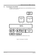
Page 56: ...s with the RDC G Advantages of this concept An optimally adapted processor RISC DSP can be selected for the drive section on the DSEAT The software implementation on the PC processor CISC Processor Pe...

Page 57: ...SP Digital Signal Processor RAM EEPROM and interfaces to the RDC and to the PM6 600 SSI synchronous serial interface the same data block every 125 s Interface connector to MFC Processor TMS320C32 Inte...

Page 58: ...the following error Position control is implemented on the DSEAT in order to relieve the load on the main processor Speed controller This controller corrects the motor speed The actual speed i e the i...

Page 59: ...ing the DSEAT card G Switch off the system and wait until the battery backed shutdown storage procedure is terminated G Release the card retainer butterfly screw G Disconnect all lines to the KVGA MFC...

Page 60: ...display is too slow to show the individual values The 2nd to 9th word axis X shows the resolver positions of the individual axes These values will normally vary if the value of the relevant axes is 00...

Page 61: ...n increments Resolver position this value is compared to the actual resolver position on power up tolerance 6 increments in increments Calibration data offset symmetry Moreover this EEPROM also contai...

Page 62: ...plexer 16 1 cos sampling Processor TMS320C32 60 MHz Local RAM 32K x 32 12 V 1 Synchronous serial interface Motor temperature Resolver interface EE pot amplitude adjustment Logic DSP Driver Amplifier M...

Page 63: ...r evaluation The resolver response signals 8 x SIN and 8 x COS are fed to 2 multiplexers and then con verted from analog to digital signals A D conversion takes place at every peak value of the carrie...

Page 64: ...812 X21 X21 X31 X31 Frei 1 GND 7 2 2 2 2 2 2 14 14 24V 7 3 3 3 3 3 3 15 15 CLKo 1 4 4 4 4 4 4 10 10 CLKo 1 5 5 5 5 5 5 11 11 FSi 6 6 6 6 6 6 6 7 7 FSi 6 7 7 7 7 7 7 6 6 Di 4 8 8 8 8 8 8 9 9 Di 4 9 9 9...

Page 65: ...INT0 default Fig 40 Configuration of the RDC card 7 5 RDC interfaces X1 Resolver axis 1 Connector Lumberg X2 Resolver axis 2 Connector Lumberg X3 Resolver axis 3 Connector Lumberg X4 Resolver axis 4 C...

Page 66: ...fully disconnect all connections to the RDC X1 to X6 X9 and X10 and bend them to one side so that they are out of the way G Unscrew and carefully remove the fixings of the RDC G Check the configuratio...

Page 67: ...ot run ning correctly 7 7 2 1 Displaying the RDC table G Select menu option 1 Show RDC table Items 0 to 7 show the motor temperature of the individual axes Press the space bar several times to refresh...

Page 68: ...whether more than 3 consecutive transmissions have failed If so the status value is 1 Under normal conditions this value is 0000 If the status is 1 DSEAT RDC communication is disrupted by fault condit...

Page 69: ...he values are correct press key Y to accept the values of the RDC and to load them into the EEPROM if the values are incorrect press key N to refuse the values from the RDC and reset the RDC to its de...

Page 70: ...ry backed shutdown storage procedure is terminated G About one minute after shutdown switch the system on again G When the system has run up recheck the LEDs on the RDC lit and DSEAT flashing G Check...

Page 71: ...Data cable connector 51 E Emergency Stop circuit 39 Ethernet Sub D connector X802 50 I Interface signals 37 J Jumpers for stand alone operation 54 K KCP connector X19 53 P Peripheral connector 48 Peri...

Reviews: