background image

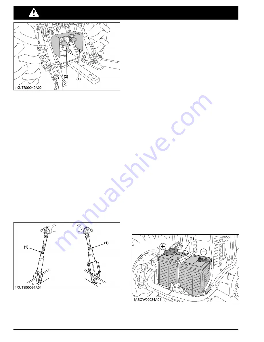
(1) PTO shaft cover

(2) PTO shaft cap

• Before  installing  or  using  PTO  driven  equipment,

read  the  manufacturer's  manual  and  review  the
safety labels attached to the equipment.
To prevent PTO driven equipment from improper or
unsafe  use,  select  the  lower  speed  (540  rpm)
unless the higher one is specifically recommended
as safe by the equipment manufacturer.

• When  operating  stationary  PTO  driven  equipment,

always  apply  the  tractor  parking  brake  and  place
chocks behind and in front of the rear wheels. Stay
clear  of  all  rotating  parts.  Never  step  over  rotating
parts.

USING 3-POINT HITCH

• Use the 3-point hitch only with equipment designed

for the appropriate category of 3-point hitch usage.

• When using a 3-point hitch mounted implement, be

sure to install the proper counterbalance weight on
the front of the tractor.

• To avoid injury from separation:

Do not extend the lift rod beyond the groove on the
threaded rod.

(1) Groove

SERVICING THE TRACTOR

Before  servicing  the  tractor,  park  it  on  a  firm,  flat  and
level  surface,  set  the  parking  brake,  lower  all
implements to the ground, place the gear shift lever in
neutral, stop the engine and remove the key.

• Allow the tractor time to cool off before working on

or near the engine, muffler, radiator and so on.

• Do  not  remove  radiator  cap  while  coolant  is  hot.

When  cool,  slowly  rotate  cap  to  the  first  stop  and
allow sufficient time for excess pressure to escape
before  removing  the  cap  completely.  If  the  tractor
has a coolant recovery tank, add coolant or water to
the recovery tank, not the radiator.
(See Checking coolant level on page 105.)

• Always  stop  the  engine  before  refueling.  Avoid

spills and overfilling. Use only approved fuels.

• Always use grounded refueling facilities.
• Do  not  smoke  when  working  around  battery  or

when  refueling.  Keep  all  sparks  and  flames  away
from battery and fuel tank. The battery presents an
explosive  hazard,  because  it  gives  off  hydrogen
and oxygen especially when recharging.

• Before 

“jump  starting”

  a  dead  battery,  read  and

follow all of the instructions.
(See JUMP STARTING on page 49.)

• Keep  first  aid  kit  and  fire  extinguisher  handy  at  all

times.

• Disconnect  the  battery's  ground  cable  before

working on or near electric components.

• To avoid the possibility of battery explosion, do not

use  or  charge  the  refillable  type  battery  if  the  fluid
level is below the 

[LOWER]

 (lower limit level) mark.

Check  the  fluid  level  regularly  and  add  distilled
water as required so that the fluid level is between
the 

[UPPER]

 and 

[LOWER]

 levels.

• To  avoid  sparks  from  an  accidental  short  circuit,

always  disconnect  the  battery's  ground  cable  (-)
first and reconnect it last.

M4N-071

(1) Battery

SAFE OPERATION

12

M4N-071, M5N-091, M5N-111

Summary of Contents for M4N-071

Page 1: ...U S A Code No 3B481 9971 4 M5N 091 M5N 111 M4N 071 MODELS OPERATOR S MANUAL 1ABCW00001A01 1ABCW00051A01 M 4 N 0 7 1 M 5 N 0 9 1 M 5 N 1 1 1 KUBOTA Corporation 2017 PRINTED IN JAPAN READ AND SAVE THIS...

Page 2: ...n KUBOTA M4N 071 M5N 091 M5N 111 AY A 5 6 2 AK Abbreviations Definitions ABBREVIATION LIST 2 Wheel Drive 4 Wheel Drive American Petroleum Institute American Society of Agricultural and Biological Engi...

Page 3: ...d operating hours Engine coolant temperature Low temperature regulation Engine intake combustion air filter Engine oil pressure Water separator Engine warning Engine rev limiter Engine constant rpm ma...

Page 4: ...PTO 540 rpm PTO 540E rpm Hydraulic related Draft control shallow position Draft control deep position Position control raised position Position control lowered position 3 point lowering speed control...

Page 5: ......

Page 6: ......

Page 7: ...edures 38 5 Operating procedure for parked regeneration 39 6 Tips on diesel particulate filter DPF regeneration 40 SELECTIVE CATALYTIC REDUCTION SCR MUFFLER 40 1 Outline of the SCR 40 2 DEF AdBlue 40...

Page 8: ...59 19 4WD and Bi speed turn switch 59 19 1 Front wheel drive and Bi speed turn usage 60 20 Hand throttle lever 60 21 Foot throttle 60 STOPPING THE TRACTOR 60 CHECK DURING DRIVING 61 1 Engine over spee...

Page 9: ...ft control 81 3 Mixed control 81 4 Float control 82 5 3 point hitch lowering speed knob 82 REMOTE HYDRAULIC CONTROL SYSTEM 82 1 Remote control valve 82 2 Remote control valve lever 83 3 Remote control...

Page 10: ...ng engine oil 108 2 Replacing engine oil filter 108 EVERY 50 HOURS 108 1 Checking engine start system 108 1 1 Preparation before testing 108 1 2 Testing switch for the shuttle shift lever 108 1 3 Test...

Page 11: ...PCV valve 127 6 Checking and cleaning EGR cooler 127 EVERY 2000 HOURS OR 2 YEARS 127 1 Flushing cooling system and changing coolant 127 2 Antifreeze 128 EVERY 3000 HOURS 129 1 Checking turbocharger 1...

Page 12: ...ing water 132 4 Replacing fuses 132 5 Replacing slow blow fuses 133 5 1 Replacement procedure 134 6 Replacing light bulb 134 7 Replacing head lamp 134 STORAGE 136 TRACTOR STORAGE 136 REMOVING THE TRAC...

Page 13: ...plements meeting the specifications listed in this manual or implements approved by KUBOTA See IMPLEMENT LIMITATIONS on page 27 Use proper weights on the front or rear of the tractor to reduce the ris...

Page 14: ...and the power take off PTO are disengaged or OFF Fasten the seat belt if the tractor has a CAB a fixed ROPS or a foldable ROPS in the upright and locked position Do not start engine by shorting acros...

Page 15: ...he lungs silicosis Because crystalline silica is a basic component of sand and granite many activities at construction sites produce dust containing crystalline silica Trenching sawing and boring of m...

Page 16: ...then shift the shuttle lever Start off after selecting shuttle direction by releasing the clutch pedal When driving down a slope ensure that 4 wheel drive is engaged to increase traction and braking e...

Page 17: ...trol levers in their neutral positions set the parking brake stop the engine remove the key from the ignition and lock the CAB door if equipped Leaving transmission in gear with the engine stopped wil...

Page 18: ...or and so on Do not remove radiator cap while coolant is hot When cool slowly rotate cap to the first stop and allow sufficient time for excess pressure to escape before removing the cap completely If...

Page 19: ...all connections are tight and that all lines pipes and hoses are free of damage Fluid escaping from pinholes may be invisible Do not use hands to search for suspected leaks use a piece of cardboard or...

Page 20: ...ion and can be punishable by your local laws and regulations When draining fluids from the tractor place a container underneath the drain port Do not pour waste onto the ground down a drain or into an...

Page 21: ...SAFETY LABELS SAFE OPERATION M4N 071 M5N 091 M5N 111 15...

Page 22: ...SAFE OPERATION 16 M4N 071 M5N 091 M5N 111...

Page 23: ...SAFE OPERATION M4N 071 M5N 091 M5N 111 17...

Page 24: ...SAFE OPERATION 18 M4N 071 M5N 091 M5N 111...

Page 25: ...d or missing safety labels with new labels from your local KUBOTA Dealer If a component with safety label s affixed is replaced with new part make sure new label s is are attached in the same location...

Page 26: ...20 M4N 071 M5N 091 M5N 111...

Page 27: ...u purchased your machine or your local KUBOTA Dealer When in need of parts be prepared to give your dealer the product identification number PIN and the CAB ROPS and engine serial numbers Locate the P...

Page 28: ...of which may be obtained from your selling dealer No warranty shall however apply if the tractor has not been handled according to the instruction given in the operator s manual even if it is within...

Page 29: ...Maximum torque N m rpm ft lbs rpm 270 1500 199 1500 307 1500 226 1500 345 1500 254 1500 Battery capacity 12V RC 160 min CCA 900A Fuel tank capacity L U S gals 76 20 1 Engine oil capacity L U S qts 10...

Page 30: ...ts 3 kg lbs 2300 5071 24 in behind lifting point 3 kg lbs 1500 3307 Remote hydraulic control 2 standard valves System pressure MPa kgf cm2 19 1 195 Traction system Rigid drawbar PTO Live PTO in depend...

Page 31: ...4 4 3 2 7 5 5 3 3 3 6 7 6 4 7 1 9 6 6 0 2 13 1 8 2 3 16 0 10 0 4 21 9 13 7 5 27 0 16 9 6 35 5 22 2 Reverse Creep option 1 0 27 0 17 2 0 38 0 23 3 0 46 0 29 4 0 63 0 39 5 0 77 0 48 6 1 11 0 69 1 1 9 1...

Page 32: ...1 11 0 6 8 3 16 0 10 0 15 8 9 9 13 3 8 3 4 21 9 13 7 21 7 13 5 18 2 11 4 5 27 0 16 9 26 8 16 7 22 5 14 1 6 35 5 22 2 35 1 21 9 29 5 18 5 Reverse Creep option 1 0 27 0 17 0 28 0 17 0 23 0 15 2 0 38 0 2...

Page 33: ...d max hydraulic lifting capacity W1 Implement weight the implement s weight which can be put on the lower link W2 Max drawbar load W3 Trailer loading weight the max loading weight for trailer NOTE Imp...

Page 34: ...ller Max tilling width mm in 2130 84 Max weight kg lbs 800 1760 5 Bottom plow Max size 14 in x 3 16 in x 2 18 in x 1 Max weight kg lbs 3P type 450 1000 6 Disk harrow 3P type Max size 18 in x 24 Max ha...

Page 35: ...6 4 Steering wheel tilt pedal 53 5 Turn signal and headlight switch 54 6 Front work light switch 55 7 Constant RPM Management switch 69 8 DPF inhibit switch 37 9 Parked regeneration switch 39 10 4WD a...

Page 36: ...v limiter indicator 58 14 Fuel level indicator 61 15 Emission indicator 61 16 DEF AdBlue system warning indicator M5N 091 M5N 111 61 17 DEF AdBlue warning indicator M5N 091 M5N 111 61 18 Regeneration...

Page 37: ...Remote control valve lever 83 10 Dual speed shift switch dual speed model for M5N 091 M5N 111 59 11 Hand throttle lever 60 12 RPM dual memory switch 68 13 PTO clutch control switch 73 14 Position con...

Page 38: ...coolant level Check water separator Clean grill and radiator screen Clean intercooler Clean fuel cooler Clean oil cooler Check DPF muffler M4N 091 Check DPF SCR muffler M5N 091 M5N 111 Check air clean...

Page 39: ...m hot exhaust gases During regeneration white exhaust gases may be visible Do not allow regeneration in an unventilated garage or confined area During regeneration do not leave the tractor NOTE Exhaus...

Page 40: ...2 DPF regeneration process DPF regeneration process can be performed by choosing Auto regeneration or Regeneration inhibit mode according to your job conditions For jobs not affected by hot gases emit...

Page 41: ...uilt up in the DPF Continue to operate the tractor and the regeneration process will begin automatically make sure the working place is in a safe area as DPF and exhaust temperature will rise 3 When t...

Page 42: ...PF system is now in Level 2 The regeneration indicator starts flashing Start the regeneration referring to PM warn ing level 1 above Now the parked regeneration indicator starts flashing and the parke...

Page 43: ...the DPF inhibit switch and the switch lamp illuminates Switch lamp ON Regeneration inhibit mode selected Switch lamp OFF Auto regeneration mode selected 3 When the parked regeneration indicator start...

Page 44: ...procedure for parked regener ation on page 39 PM warning level 2 2 Buzzer Sounding every 3 sec onds The parked regeneration indicator starts flashing PM warning level 3 Buzzer Sounding every 1 second...

Page 45: ...eration cycle do not touch the above levers and switches in steps 2 3 4 nor change the engine rpm other than for an emergency stop Otherwise the regeneration will be interrupted Never leave the tracto...

Page 46: ...t temperature Because of this the engine may sound differently but this is normal for this engine Just after the regeneration has ended the DPF muffler remains hot It is advisable to keep the engine r...

Page 47: ...AdBlue 4 Performance monitor error code and DTC 3 2 SCR system icon on inducement display Low level icon of DEF AdBlue Trouble icon of SCR system Poor quality icon of DEF AdBlue Freeze icon of DEF AdB...

Page 48: ...ne output will be limited to idle status limited engine output Lv 2 inhibit 3 The amount of remaining DEF AdBlue has dropped below 5 of the maximum capacity The engine output will remain limited Refil...

Page 49: ...t to the icon represents the limited engine output level Lv 1 Level 1 Within 50 of max torque and 60 of engine speed Lv 2 Level 2 Within engine near idling speed After an error has occurred it may be...

Page 50: ...fault has not been detected over 40 hours from the repair If a fault is detected after the 40 hours warning record reset then the new countdown will be stated OPERATING THE ENGINE SELECTIVE CATALYTIC...

Page 51: ...ING THE ENGINE 1 Make sure the parking brake is set Pull the parking brake lever to parking position The parking brake warning indicator on the Easy Checker will come on while the parking brake is set...

Page 52: ...Insert the key into the key switch and turn it ON If the ambient temperature is below 0 32 and the engine is very cold turn the key to ON position and hold it until the heater indicator turns off OFF...

Page 53: ...utomatically when preheat is completed Illumination time of indicator varies according to the temperature of coolant 3 The PTO clutch indicator 3 comes on while PTO clutch control switch is engaged ON...

Page 54: ...ertreatment system prior to completion may damage the system or cause it to malfunction NOTE If removing the key does not stop the engine consult your local KUBOTA Dealer Some noise heard for a couple...

Page 55: ...the positive red or positive terminal of the dead battery and clamp the other end of the same cable to the positive red or positive terminal of the helper battery 5 Clamp the other cable to the negat...

Page 56: ...bricating oil for new tractors The lubricating oil is especially important in the case of a new tractor The various parts are not broken in and are not accustomed to each other Small metal grit may de...

Page 57: ...nal injury Make sure that both lock pins are properly installed and secured with the lynch pins 1 ROPS 2 Lynch pin 3 Lock pin 4 Cushion 2 Raising the ROPS to upright position 1 Remove both lynch pins...

Page 58: ...brake pedals and release the parking brake lever Parking brake lever on page 56 7 Depress the clutch pedal Clutch pedal on page 56 8 Selecting the travel speed Travel speed control on page 57 Travel...

Page 59: ...onal injury or death Do not touch the muffler pipe or muffler while the engine is running or while muffler pipes are hot The high temperature will cause burning Remove all weeds straw and combustible...

Page 60: ...the turn signal light switch counter clockwise The corresponding right and left turn signal lights and indicator on the instrument panel will flash NOTE The hazard light switch is operative when the k...

Page 61: ...d shifting forward or loss of control To avoid skidding and loss of steering control when driving on icy wet or loose surfaces make sure the tractor is correctly ballasted operated at reduced speed an...

Page 62: ...lever 2 Release button A TRANSPORT POSITION NOTE The parking brake warning indicator on the Easy Checker will turn off when the parking brake is unlocked If the shuttle shift lever is moved when the...

Page 63: ...ft switch if equipped range gear shift lever and shuttle shift lever combination the forward speeds and reverse speeds shown in the following table are obtained Standard model F12 R12 without creep 12...

Page 64: ...tractor be sure to apply the parking brake and stop the engine In applying the brakes The torque of the wheel axle is extremely high while creep speed is being used Be sure to step down on the clutch...

Page 65: ...nal injury or death Do not engage the front wheel drive when traveling at road speed When driving on icy wet or loose surfaces make sure the tractor is correctly ballasted to avoid skidding and loss o...

Page 66: ...When working in sandy soil When working on a hard soil where a rotary tiller might push the tractor forward For increased braking at reduced speed Bi speed turn use is effective for the following jobs...

Page 67: ...Easy Checker If the warning indicators on the Easy Checker come on during operation immediately stop the engine and find the cause as follows Never operate the tractor while an Easy Checker indicator...

Page 68: ...ker will light up If this should happen during operation refill or replace with DEF AdBlue as soon as possible See SELECTIVE CATALYTIC REDUCTION SCR MUFFLER on page 40 Emission indicator If this indic...

Page 69: ...ot remove the radiator cap until coolant temperature is well below its boiling point Then loosen the cap slightly to the first stop to relieve any pressure before removing the cap completely 1 With th...

Page 70: ...eed 64 8 Performance monitor Various information can be selected by the operator 67 NOTE Errors may occur in the fuel consumption display depending on the conditions of use Use the displayed data only...

Page 71: ...ious setting mode screen appears again 1 2 Setting the clock display ON OFF 1 Press the mode selector switch to choose Clock ON OFF setting Then press the select switch and the clock ON OFF setting sc...

Page 72: ...71 18 4 16 1 R1 133 338 320 85 R20 123 312 480 65 R24 148 376 3 Press the mode selector switch 4 To complete the setting select Set with the select switch The various setting mode screen appears again...

Page 73: ...rs for which the tractor has been used the last digit indicates 1 10 of an hour Trip meter The total operating hours counted from the previous re setting is displayed 2 4 Instantaneous fuel con sumpti...

Page 74: ...ngine revolution is less than the rpm memory setting value Work During work simply press the switch to the A side to auto matically set an engine speed of 2000 rpm Turning When turning press the switc...

Page 75: ...ored even after the engine is stopped Canceling the setting Any of the actions below will cancel the RPM dual memory settings 1 For the switch A side when the memory speed is engaged press the switch...

Page 76: ...anipulation of the travel speed and hand throttle lever There is a limit to the range within which a constant speed can be maintained If a load exceeding the engine performance is applied the engine s...

Page 77: ...A Dealer for further details 1 SMV emblem 2 Bracket 3 Operating on slopes and rough terrain WARNING To avoid personal injury or death Always back up when going up a steep slope Driving forward could c...

Page 78: ...he power steering mechanism makes the steering easier Be careful when driving on the road at high speeds 6 Trailer electrical outlet A trailer electrical outlet is supplied for use with a trailer or i...

Page 79: ...open the throttle to the recommended speed NOTE Tractor engine will not start if PTO clutch control switch is in the engaged ON position If the PTO system is engaged and you stand up from the seat the...

Page 80: ...Move the PTO gear shift lever to 540E and then turn on the PTO clutch control switch and the rev limiter indicator lights up on the meter panel If the PTO clutch control switch is turned on with the e...

Page 81: ...e PTO shaft cap when the PTO is not in use Before connecting or disconnecting a drive shaft to the PTO shaft be sure the engine is OFF 1 PTO shaft cover 2 PTO shaft cap IMPORTANT The universal joint o...

Page 82: ...3 POINT HITCH AND DRAWBAR 1 Top link 2 Lifting rod left 3 Stabilizer 4 Lower link 5 Lifting rod right 6 Drawbar 3 POINT HITCH AND DRAWBAR 76 M4N 071 M5N 091 M5N 111...

Page 83: ...electing the holes of lower links There are 2 holes in the lower links For most operations the lifting rods should be attached to the B hole 1 Lower link 2 Lifting rod 3 Split pin 4 Nut 5 Lift rod pin...

Page 84: ...SITION B UNLOCK POSITION 6 Top link 1 Adjust the angle of the implement to the desired position by shortening or lengthening the top link 2 The proper length of the top link varies according to the ty...

Page 85: ...ward to release it from the turnbuckle 3 Rotate the hex wrench handle and slide it backward until the hexagonal part is locked on the turnbuckle 4 Repeat steps 1 to 3 until the desired stabilizer leng...

Page 86: ...ing drawbar length 1 When towing an implement it is recommended that hole A in drawbar be utilized 2 For information about the drawbar load read the implement limitations section of this manual See IM...

Page 87: ...and tractor when operating the 3 point hitch controls 1 Position control This will control the working depth of the 3 point hitch mounted implement regardless of the amount of pull required 1 Positio...

Page 88: ...e 3 types of remote valves available for these models Double acting valve with detents and self canceling This valve may be placed in the detent mode The lever will stay in this position until the pre...

Page 89: ...de tents and self canceling B Double acting valve with float position C Single or double acting valve Pressure Returning Double acting valve with detents and self canceling Lever 1 Lever position Z de...

Page 90: ...ust from the coupler then replace the dust plugs NOTE Your local KUBOTA Dealer can supply parts for adapting couplers to hydraulic hoses 4 Controlling and adjusting the flow rate WARNING To avoid the...

Page 91: ...ng RPM turn the flow control knob once all the way clockwise C and then turn it gradually counterclockwise until a required flow rate is reached NOTE Oil from the pump flows by priority to the auxilia...

Page 92: ...oldboard plow Light soil Medium soil Heavy soil 3 2 or 3 2 Draft and mixed control place the draft control lever to the suitable position and set the imple ment pull with the position control lev er Y...

Page 93: ...f cm2 23 psi 380 85R24 6PR 138 kPa 1 4 kgf cm2 20 psi 380 85R24 165 kPa 1 7 kgf cm2 24 psi 320 85R20 160 kPa 1 6 kgf cm2 23 psi 480 65R24 160 kPa 1 6 kgf cm2 23 psi 2 Dual tires Dual tires are not app...

Page 94: ...s attach wheels as shown in the drawing If not attached as illustrated transmission parts may be damaged When re fitting or adjusting a wheel tighten the bolts to the following torques then recheck af...

Page 95: ...in 9 5 16 1150 mm 45 3 in 1250 mm 49 2 in 280 70R18 1235 mm 48 6 in 1 Rear wheel disc 2 Tread 2 1 Front jack point WARNING To avoid personal injury or death Before jacking up the tractor park it on a...

Page 96: ...10 times of shuttle movement by 5 m 5 yards and thereafter according to service interval See MAINTENANCE on page 94 1 2 Steel disk Cast iron disk 260 to 304 N m 26 5 to 31 0 kgf m 191 8 to 224 2 ft lb...

Page 97: ...055 mm 41 5 in 1160 mm 45 7 in 1270 mm 50 0 in 1 Rear wheel disc 2 Rear wheel rim 3 Tread 18 4 16 1 1170 mm 46 1 in 1 Rear wheel disc 2 Tread WHEEL ADJUSTMENT TIRES WHEELS AND BALLAST M4N 071 M5N 091...

Page 98: ...needed 1 1 Front end weights option Front end weights can be attached to the bumper See your implement operator s manual for required number of weights or consult your local KUBOTA Dealer about their...

Page 99: ...or this service Liquid weight per tire 75 filled Tire sizes 12 4 24 380 85R24 Slush free at 24 11 Solid at 47 53 Approx 1 5 kg 3 5 lbs CaCl2 per 4 L 1 gal of water 139 7 kg 308 lbs 215 0 kg 474 lbs Sl...

Page 100: ...axle gear case oil Change 125 Engine valve clear ance Adjust 126 1 Continued Interval Items Ref page I every 1000 Hr or 1 year 6 Air cleaner primary element Replace 126 Air cleaner secon dary element...

Page 101: ...the indicator annually 4 The initial 50 hours should not be a replacement cycle 5 Replace if any deterioration crack hardening scar or defor mation or damage occurred 6 Every 1000 hours or every 1 ye...

Page 102: ...00 1350 1400 1450 1500 1550 1600 1650 1700 1750 1800 1850 1900 Continued Hour meter Maintenance items A B C D E F G H I J K L M N O P 1950 2000 2050 2100 2150 2200 2250 2300 2350 2400 2450 2500 2550 2...

Page 103: ...pose grease NLGI 2 or NLGI 1 GC LB Top link bracket 2 Lift rod 2 Hydraulic lift cylinder pin 4 Front axle gear case support 2 Front axle support 2 Steering joint shaft 1 Battery terminal 2 A small amo...

Page 104: ...s stations truck stops and specialty shops Be sure to use the genuine product only Use exclusively DEF AdBlue that complies with the requirements of ISO 22241 1 Transmission oil KUBOTA Super UDT2 For...

Page 105: ...hen using BDF the owner is advised to check applicable local and federal emission regulations and comply with all of them 2 BDF may cause restricted or clogged fuel filters during cold weather conditi...

Page 106: ...ult your local KUBOTA Dealer for this service Long term storage 1 BDF easily deteriorates due to oxygen water heat and foreign substances Do not store B6 through B20 longer than 1 month and B5 longer...

Page 107: ...d oil fuel coolant hydraulic fluid urea aqueous solution DEF AdBlue refrigerant solvent filters rubber batteries and harmful substances can harm the environment people pets and wildlife Please dispose...

Page 108: ...firm and level ground Set the parking brake Lower the implement to the ground Release all residual pressure from the hydraulic system Stop the engine and remove the key 1 Walk around inspection Look...

Page 109: ...death Before adding DEF AdBlue stop the engine When adding the fluid preferably wear protective goggles and rubber gloves IMPORTANT The DEF AdBlue tank cap is blue Be careful not to confuse it with t...

Page 110: ...er separator indicator on the instrument panel lights up and a warning buzzer sounds 1 Water separator indicator 2 In this case close the fuel shutoff valve and loosen the air plug and drain plug by s...

Page 111: ...off the engine 2 To check the oil level draw out the dipstick wipe it clean replace it and draw it out again Check to see that the oil level lies between the 2 notches If the level is too low add new...

Page 112: ...icator on the air cleaner body If the red signal on the dust indicator is visible clean the element immediately See Cleaning air cleaner primary element on page 111 Reset the red signal by pushing a R...

Page 113: ...muffler WARNING To avoid personal injury or death Before checking or cleaning the DPF SCR muffler stop the engine and wait until it cools down enough Check the DPF SCR muffler and its surroundings fo...

Page 114: ...do not attempt to force them into motion In the above case remove the rust or the sticky material and apply oil or grease to the relevant spot Otherwise the machine may be damaged INITIAL 50 HOURS Wi...

Page 115: ...ge the PTO clutch control switch or lever The PTO should begin to rotate Disengage the PTO clutch control switch or lever 6 While getting up from the operator s seat engage the PTO clutch control swit...

Page 116: ...e to the following points every 100 hours If you have been operating the machine in extremely wet and muddy conditions lubricate the grease fittings more often 1 Grease fitting front axle support 1 Gr...

Page 117: ...yearly whichever comes first NOTE Check to see if the evacuator valve is blocked with dust 1 Secondary safety element 2 Primary element 3 Evacuator valve 4 Cover IMPORTANT The air cleaner uses a dry e...

Page 118: ...djusting bolt to adjust the belt tension within acceptable limits 4 Replace fan belt if it is damaged IMPORTANT Make sure that the V belt tension is as specified as shown in the table above after tigh...

Page 119: ...sibility of battery explosion For the refillable type battery follow the instructions below Do not use or charge the refillable type battery if the fluid level is below the LOWER lower limit level mar...

Page 120: ...s are securely in place if equipped When disconnecting the cable from the battery start with the negative terminal first When connecting the cable to the battery start with the positive terminal first...

Page 121: ...he straight ahead position 3 Lower the implement apply the parking brake and stop the engine 4 Measure the distance between the tire beads at the front of the tire at hub height 5 Measure the distance...

Page 122: ...mble the water separator keeping out dust and dirt 6 Connect the water sensor connector 7 Bleed the fuel system See Bleeding fuel system on page 131 1 Water sensor connector 2 Fuel shutoff valve 3 Cup...

Page 123: ...A TIGHTEN B LOOSEN C Pin Tighten the cover until the end of the slot contacts the pin EVERY 500 HOURS 1 Changing engine oil WARNING To avoid personal injury or death Be sure to stop the engine before...

Page 124: ...acceptable within this range M5N 091 M5N 111 1 Drain plug 2 Replacing engine oil filter WARNING To avoid personal injury or death Be sure to stop the engine before replacing the oil filter cartridge...

Page 125: ...of clean fuel on the rubber seal of the new filter 3 Tighten the filter quickly until it contacts the mounting surface Tighten the filter by hand an additional 1 2 turn only 4 Bleed the fuel system S...

Page 126: ...the new filter has been replaced fill the transmission oil up to the upper notch on the dipstick 1 Gauge A Oil level is acceptable within this range 8 After running the engine for a few minutes stop...

Page 127: ...500 hours of operation 1 If the hose clamps are loose or water leaks tighten the bands securely 2 Replace the hoses and tighten the hose clamps securely if the radiator hoses are swollen hardened or c...

Page 128: ...e engine idling unloaded 2 Allow the engine to idle unloaded for about 5 minutes before stopping it rather than stopping it suddenly 3 Keep away from the machine for another 10 minutes or while the st...

Page 129: ...5N 091 M5N 111 1 Fuel lines 2 Clamp bands M5N 091 M5N 111 1 Fuel lines 2 Clamp bands NOTE If the fuel line has been replaced be sure to properly bleed the fuel system See Bleeding fuel system on page...

Page 130: ...amps are tight and not damaged 2 If hoses and clamps are found worn or damaged replace or repair them at once 1 Lift cylinder hoses EVERY 600 HOURS 1 Adjusting front axle pivot If the front axle pivot...

Page 131: ...rain plug 1 Dipstick 2 Oil inlet A Oil level is acceptable within this range IMPORTANT Do not operate the tractor immediately after changing the transmission fluid Run the engine at medium speed for a...

Page 132: ...king exhaust manifold Consult your local KUBOTA Dealer for this service EVERY 1500 HOURS 1 Cleaning fuel injector nozzle tip Consult your local KUBOTA Dealer for this service 2 Checking DEF AdBlue inj...

Page 133: ...ure to escape before removing the cap completely 1 Stop the engine remove the key and let it cool down 2 To drain the coolant open the radiator drain plug remove the drain plug and remove the radiator...

Page 134: ...he radiator cap If the cap is loose or improperly fitted water may leak out and the engine could overheat 2 Antifreeze WARNING To avoid personal injury or death When using antifreeze put on some prote...

Page 135: ...system 5 Adding the LLC a Add only water if the mixture level is reduced by evaporation b If there is a mixture leak add LLC of the same manufacturer and type in the same mixture percentage IMPORTANT...

Page 136: ...s service 3 Checking EGR pipe Consult your local KUBOTA Dealer for this service EVERY 2 YEARS 1 Replacing oil separator hose Consult your local KUBOTA Dealer for this service 2 Replacing boost sensor...

Page 137: ...he water separator When the tank is completely empty After the tractor has not been used for a long period of time Bleeding procedure is as follows 1 Fill the fuel tank with fuel and open the fuel shu...

Page 138: ...r the clutch housing After operating in the rain or snow or if the tractor has been washed water may get into the clutch housing Remove the drain plug drain the water and then reinstall the plug M4N 0...

Page 139: ...30 A CRS system fuel pump 2 20 A SCR system 3 30 A SCR heater system 4 10 A NOX sensor SCR tank sensor 5 10 A EGR valve air flow sensor 6 10 A Spare fuse 7 30 A Spare fuse Oil separator fuse if equip...

Page 140: ...procedure Non bolt fixed slow blow fuse 1 Disconnect the negative cord of the battery 2 Pull out the fuse from the fuse box 3 Replace with a new one of the same capacity Bolt fixed slow blow fuse Cons...

Page 141: ...l connector 2 Turn the cover counterclockwise to remove it 3 Turn the bulb base counterclockwise to take out the bulb 4 Replace it with a new bulb and reinstall the head lamp assembly in the reverse o...

Page 142: ...lue See SELECTIVE CATALYTIC REDUCTION SCR MUFFLER on page 40 10 Keep the tractor in a dry place where the tractor is sheltered from the elements Cover the tractor 11 Store the tractor indoors in a dry...

Page 143: ...k to see if the slow blow fuse of the intake air heater blows Check to see if the intake air heater functions in cold weather Insufficient engine power Insufficient or dirty fuel The air cleaner is cl...

Page 144: ...OTA Dealer If the warning indicator lights up the following phenomena may appear de pending on the engine s trouble spot The engine stops unexpected The engine fails to start or gets interrupted just...

Page 145: ...nsor main sub phase shifting trouble ERROR 7 Shuttle sensor signal trouble ERROR 8 Gear lock signal trouble ERROR 11 PTO relay trouble ERROR 12 4 wheel drive solenoid trouble ERROR 13 Bi speed turn so...

Page 146: ...ast iron disk Creep speed kit Double acting remote hydraulic control valve with detents and self canceling and flow control functions Double acting remote hydraulic control valve with float position a...

Page 147: ...ke system bleeding 132 braking system 4WD 55 C clock setting 65 clock display setting ON OFF 65 clutch housing water draining 132 clutch pedal 56 constant RPM Management control 69 coolant 97 changing...

Page 148: ...ator checking 47 Easy Checker indicators 61 EGR cooler checking 127 EGR cooler hose replacing 130 EGR pipe checking 130 EGR system checking 129 cleaning 129 electrical outlet 72 electrical outlet for...

Page 149: ...king 108 hood 101 hydraulic control unit reference chart 86 hydraulic oil filter replacing 119 I implement limitations 27 inducement display SCR system 41 instrument panel 30 intake air heater checkin...

Page 150: ...k point 92 rear turn signal light switch 54 rear wheel weights option 92 rear wheels tread adjusting 90 remote control valve 82 remote control valve coupler connecting 84 disconnecting 84 remote contr...

Page 151: ...rom storage 136 scrapping procedure 22 servicing 12 starting 52 starting to operate 8 stopping 60 storing procedure 136 transporting safely 71 working 8 tractor new changing lubricating oil 50 operati...

Page 152: ......

Reviews: