MDX [en-US]
29
In Limited End Float (LEF) bearing assemblies the drive end radial bearing will be a single row taper roller bearing.
These bearings are hot when installed and are press fitted to the shaft. It is difficult to remove them from the shaft
undamaged, and they should be removed only if a bearing needs to be replaced. Bearings are normally removed by
pressing or heating. Care must be taken to avoid damaging the shaft, especially the bearing seat and shaft oil seal
areas.
In bearing assemblies with impeller release rings and some of the limited end float type, the impeller end radial bearing
may also be press fitted to the shaft. The same procedures as noted above should be followed.
The thrust bearing located between the radial bearings near the drive end is a spherical roller bearing. It is seated on
a split ring which is clamped to a thrust groove in the shaft. A one piece thrust collar is used between the bearing and
the split ring. A small amount of heat on the back of the bearing is typically enough to allow it to be pushed off the split
ring and removed from the shaft.
8.3
Mechanical End Assembly
WARNING
Refer to Section 2.9 "Assembly & Disassembly Safety" prior to working on the pump.
CAUTION
Before assembly, thoroughly clean all shaft, housing bore, and end cover surfaces with a suitable solvent to
remove old grease and any water, dust or grit. Clean all dismantled components and check them for signs of
wear. Damaged or worn components are to be replaced by original equipment spare parts. Make sure that the
seal faces are clean and the O-rings and gaskets are properly fitted.
8.3.1
Mounting the Bearings
WARNING
Care must be taken when handling heated components.
CAUTION
If you are using hand glued o-rings between the seals and the housing, their joints must be of the highest quality
or oil leakage and seal failure may occur. Place the o-ring joint at the 12 o’clock position.
Shaft Size
Typical
Radial
Bearing
Typical Un-mounted Internal Clearance
Required Decrease for
Mounting
Class C3
Class CN
inch
/1000
mm
inch
/1000
mm
inch
/1000
mm
2 – 15/16
22217C3
4.4 – 5.7
0.112 – 0.115
3.2 – 4.4
0.081 – 0.112
1.7 – 2.5
0.046 – 0.064
3 – 15/16
22222C3
5.3 – 6.9
0.135 – 0.176
3.9 – 5.3
0.099 – 0.135
2.0 – 2.8
0.051 – 0.071
4 – 7/16
22226C3
6.3 – 8.1
0.160 – 0.206
4.7 – 6.3
0.119 – 0.160
2.5 – 3.5
0.064 – 0.089
5 – 7/16
22332C3
7.1 – 9.1
0.180 – 0.231
5.1 – 7.1
0.130 – 0.180
3.0 – 4.0
0.076 – 0.102
6 – 7/16
22336C3
7.9 – 10.2
0.201 – 0.259
5.5 – 7.9
0.140 – 0.201
3.0 – 4.5
0.076 – 0.114
7 – 3/16
22340C3
8.8 – 11.4
0.226 – 0.290
6.3 – 8.8
0.160 – 0.224
3.5 – 5.0
0.089 – 0.127
9
23252C3
11.8 – 15.6
0.300 – 0.396
8.7 – 11.8
0.221 – 0.300
4.5 – 6.5
0.114 – 0.165
10 – 1/4
23256C3
11.8 – 15.4
0.300 – 0.391
8.7 – 11.8
0.221 – 0.300
4.5 – 6.5
0.114 – 0.165
11 – 1/2
23264C3
14.2 – 18.7
0.361 – 0.475
10.6 – 14.2
0.269 – 0.361
6.0 – 8.5
0.152 – 0.216
Mounted Clearance = Un-mounted clearance
–
Required Decrease
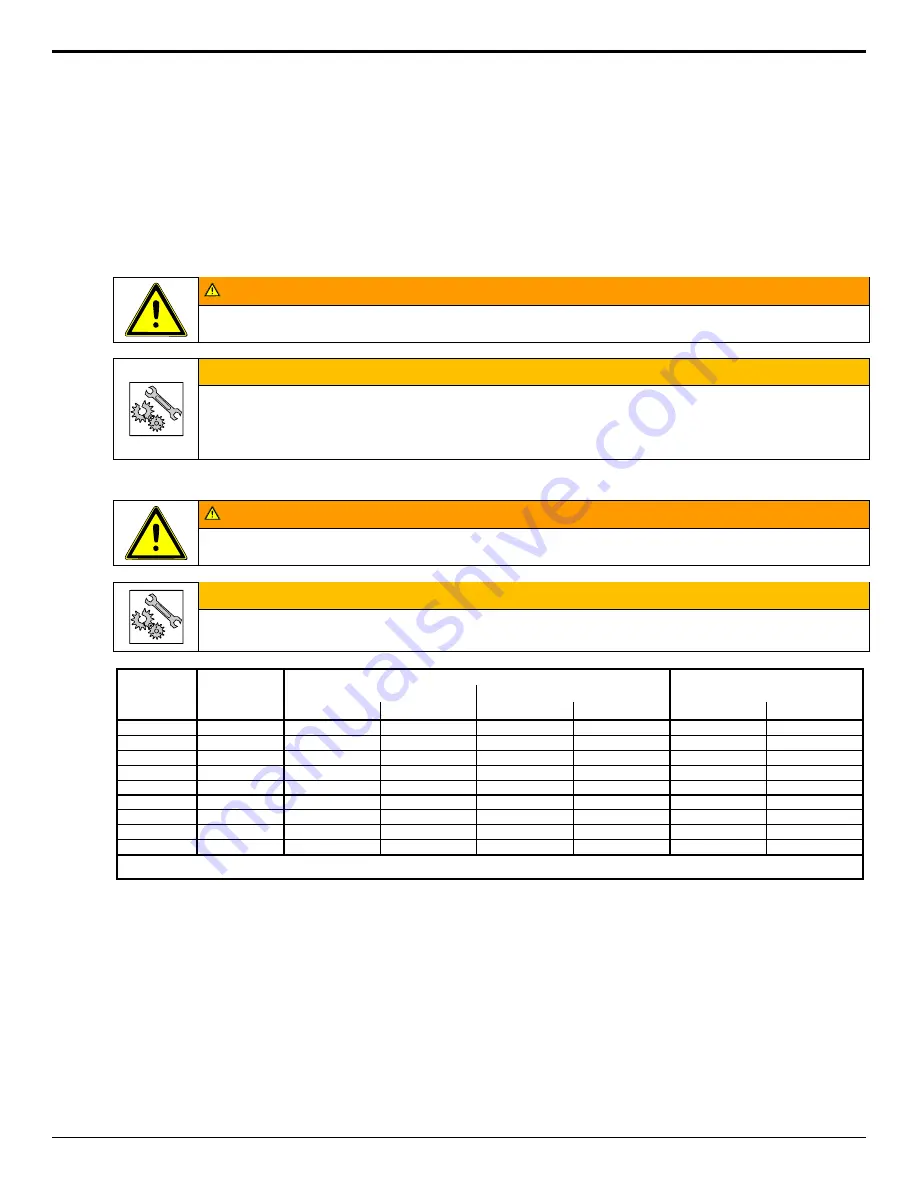
Mounting Clearances for Radial Bearings
Place the thrust bearing on the shaft.
Bolt the split thrust collar (or split ring plus thrust collar in larger sizes), into place at the mating groove on the shaft.
The thrust bearing is a drive fit on the thrust collar. The application of a little heat will aid in its seating. The bearing
should be pressed fully against the thrust collar shoulder.
Before mounting the bearings, the radial bearings should be placed upright on a level surface with one roller at the 12
o’clock position. Use a feeler gauge to measure the internal clearance between this roller and the outer race. Record
this value as “Un-mounted Clearance”.
Bearings with straight bores and no locknuts are press fit on the shaft. Heat bearings to 105 °C (220 °F) with a suitable
bearing heater, oil bath, or other even heating device prior to mounting. Flame heating is not recommended. When
mounting, be sure the bearings are fully seated against the locating shaft shoulder and held in place until the bearing
cools.
Summary of Contents for GIW MDX
Page 53: ...MDX en US 53 14 Notes...


