3/2
Installation and operating instructions
IFC 020
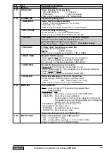
Here you can note down the settings of the signal converter !
Fct. No.
Function
Settings
1.01
Full-scale range
1.02
Time constant
1.03
Low-flow cut-off
- ON:
- OFF:
1.04
Display
Flow
Totalizer
Messages
1.05
Current output I
Function
Range I
Error
1.06
Pulse output P
Function
Selection
Pulse width
Value
1.07
Status output S
1.08
Control input E
(IFC 020 E only)
3.01
Language
3.02
Primary head
Meter size
GK value
Field frequency
Power frequency
Flow direction
3.04
Entry code required ?
- no
- yes
→ → → ↵ ↵ ↵ ↑ ↑ ↑
3.05
User-defined unit
3.06
Application
Flow is - steady
- pulsating
3.07
Measuring point
3.08
Communication interface
o
Off
o
HART
o
KROHNE RS 485
Address
Baud rate
Setting data 3.3

