Installation and operating instructions
IFC 020
8/3
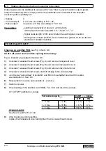
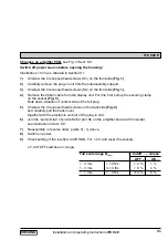
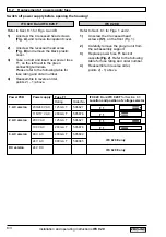
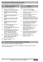
8.2 Replacement of power supply fuse
Switch off power supply before opening the housing!
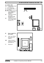
Power PCB
Power supply Fuse F1
IFC 020 K
and
IFC 020 F
for Section 8.3
Location and position of voltage selector
Rating
Order No.
1. AC version
230/240 V AC
125 mA T
5.06627
115/117 V AC
200 mA T
5.05678
2. AC version
200 V AC
125 mA T
5.06627
100 V AC
200 mA T
5.05678
3. AC version
48 V AC
400 mA T
5.05892
24 V AC
800 mA T
5.08085
DC version
24.V DC
F 1
F 1
F 1
F 1
IFC 020 K and IFC 020 F
IFC 020 E
Refer to Sect. 8.1 for Figs. A and B.
1)
Unscrew the 4 recessed head screws
(Fig. A),
and remove transparent cover.
2)
Unscrew the recessed head screw
(Fig. B)
and remove the black plastic
cover.
3)
Take out old and insert new power fuse
F1, on the left next to the green
connecting terminals.
Please refer to the following table for
fuse rating and order number.
4)
Reassemble in reverse order,
points 2) – 1) above.
Refer to Sect. 8.1 for Figs. 1 and 2.
1)
Unscrew the 4 recessed head
screws
(S1),
on the front (Fig. 1).
2)
Carefully remove the plug-in unit from
the subassembly support.
3)
Replace power fuse F1 back of
cassette
(Fig. 2)
. Refer to the following
table for fuse rating and order number.
4)
Reassemble in reverse order,
points 2) - 1) above.
IFC 020 E only
IFC 020 E only

