Installation and operating instructions
IFC 020
6/5
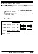
6.4 Pulsating flow
Application
downstream of positive-displacement pumps (reciprocating or diaphragm pumps) without
pulsation dampener
Operator control of the signal converter for the new settings,
see Sect. 4 and 5
To change settings
•
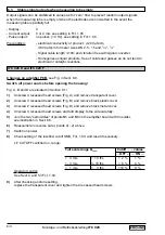
Fct. 3.02 FIELD FREQ. (change magnetic field frequency)
– Stroke frequency
less than 80 strokes/min
(at max. pump lift): do
not
change setting.
– Stroke frequency
80 - 200 strokes/min
(at max. pump lift): change setting to
1/2,
only practical with IFM 5020 K and IFS 5000 F (DN 2.5-100 /
1
/
10
”-4”)
and IFM 4020 K and F IFS 4000 F (DN 10, 15, 50-100 /
1
/
10
”,
1
/
2
”, 2”-4”),
Please consult factory where other types and meter sizes are concerned.
– Please note: given stroke frequencies close to the tripping point of 80 strokes/min, additional
measuring errors of approx. ± 0.5% of the measured value may occasionally occur.
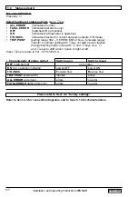
• Fct. 3.06 APPLICAT. (adjust overload point of the A/D converter to the application)
Change setting to “PULSATING”.
• Fct. 1.04 DISP. FLOW (change display presentation of flow)
Change setting to “BARGRAPH” to allow better assessment of display unsteadiness.
• Fct. 1.02 TIMECONST. (change time constant)
– Set to “ALL” and time (
t
) in seconds.
– Recommended:
t [s] =
– Example:
min. number of strokes in operation = 50 strokes/minute
t [s] =
= 20 s
With this setting, the residual ripple of the display will amount to
approx. ± 2% of the measured value. Doubling the time constant
will reduce the residual ripple by a factor of 2.
1000
min. strokes / min
1000
50 / min
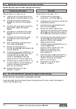
6.5 Rapid changes in flowrate
Application
in conjunction with batching processes, fast-response control loops, etc.
Operator control of the signal converter for the new settings
refer to chapters 4 and 5
To change settings
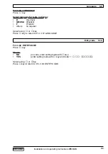
• Fct. 1.02 TIMECONST. (change time constant)
Setting to “ONLY I” and set time to 0.2 s.
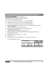
• Dynamic response with meter sizes DN 2.5-300 /
1
/
10
”-12”
Dead time:
approx. 0.06 s at 50 Hz line frequency
approx. 0.05 s at 60 Hz line frequency
Time constant: set as above, current output (mA) additionally plus 0.1 s
• Reducing the dead time by a factor of 3 (possible by changing the magnetic field frequency)
Fct. 3.02 FLOW METER, subfunction “FIELD FREQ.”, change to “1/2”,
only practical with IFM 5020 K and IFS 5000 F (DN 2.5-100 /
1
/
10
”-4”)
and IFM 4020 K and IFS 4000 F (DN 10, 15, 50-100 /
1
/
10
”,
1
/
2
”, 2”-4”)
Please consult factory where other types and meter sizes are concerned.


