background image

English


BMH 1000

Before any work on the machine itself, pull the 
mains plug!

Connect the mains cable module to the handle. The 
plug must latch.

Use the mains cable module provided only for 
Kress Electro-Tools. Do not attempt to operate 
other machines with the module.

Use only an original Kress mains cable module that is 
at least of heavy rubber sheathed cable (Code desig-
nation H07 RN-F).

Check before putting into operation that the mains 
voltage agrees with the voltage specified on the 
nameplate of the machine.

SWITCHING ON/OFF 

Press or release the on/off switch 8

The on/off switch can be locked on with the locking 
button 7. To release, briefly press and release the on/
off switch 8

MECHANICAL GEAR SELECTION

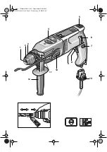
With the gear selector/rotation stop switch 4, one of 
three positions can be selected.

1 = Lower speed range: Hammer drilling, drilling 
with normal twist drills in wood/metal over 8 mm dia. 
and mixing work.

2 = Higher speed range: Drilling with normal twist 
drills to 8 mm dia.

 = No rotation: Light chiselling work.

The switch-over can best be performed at a standstill. 
Please observe that the gear selector/rotation stop 
switch 4 can be switched only one step at a time. Only 
after the on/off switch 8 is actuated and the machine 
starts does the gear box shift to the selected mode. 
The gear selector/rotation stop switch 4 can only then 
be switched again to the next position.

DRILLING - IMPACT DRILLING

For drilling, place the selector 10 in the 

 position. 

For impact drilling, set to 

The switch-over can best be performed at a standstill. 
Only after the on/off switch 8 is actuated and the 
machine starts does the gear box shift to the selected 
mode.

Note: Left rotation when impact drilling damages the 
drill. Switch off the impact mechanism for diamond 
crown drilling or for mixing work.

For chiselling work, set the selector 4 to the 

 posi-

tion. 

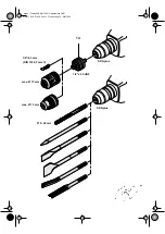
When hammer drilling, use exclusively drills with 
hard metal inserts and SDS-Plus shafts.
 The use of 
commercially available masonry drills with cylindrical 
shafts by means of the adapter 14 and the normal drill 
chuck in conjunction with the pneumatic impact mech-
anism is not possible.

SPEED CONTROL

With the on/off switch 8, the speed 
can be continuously varied.  With 
light pressure on the on/off 
switch 8, the machine begins to 
rotate slowly; with increased pres-
sure, the speed increases. 

SPEED PRESELECTION

With the knob 9, the speed in the gears 1 and 2 can 
be continuously preselected also when the machine is 
running. 

Position A = lowest speed.

Position G = highest speed. 

FULL WAVE ELECTRONIC SYSTEM WITH 
TACHOMETER

The built in full wave electronic system with tachome-
ter maintains a constant rpm speed.
The electronic system also has a gradual start up 
feature.
Even if the trigger-switch is fully depressed, the 
machine will only reach its full rpm speed after approx. 
1 second. This permits smooth drilling even when 
working with sensitive materials.

ROTATIONAL DIRECTION SWITCHING

Operate the rotational direction 
switch 6 only when the machine is 
at a standstill! 

Take hold of the rotational direction 
switch  6 on both sides. 

Right rotation:  Set the rotational direction switch 6 

to “R”. 

Left rotation: 

Set the rotational direction switch 6 
to “L”. 

Important!

Press the rotational direction 
switch 6 through to the stop on the 
housing each time, i. e., until it can 
be felt to latch.

If the rotational direction switch 6 is set between the posi-
tions “R” and “L”, the machine cannot be switched on. 

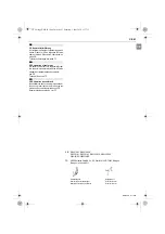
5

Mounting the Auxiliary Handle and 
the Mains Cable Module

6

Putting into Operation

BMH 1000 - Buch  Seite 8  Donnerstag 29. Mai 2006

Operate the machine only with the auxiliary han-
dle 12. Place the auxiliary handle on the clamping 
collar and tighten with the clamping screw.

Summary of Contents for BMH 1000

Page 1: ...BMH 1000 Originalbedienungsanleitung DE 4 Pneumatik Bohrhammer Original instructions EN 7 Pneumatic Drill Hammer Mode d emploi original FR 10 Perforateur pneumatique 36549_a ...

Page 2: ...Kress Titelseite BMH 1000 Hägeledruck OHG SDS plus SDS plus 1 2 x 20 UNF Ø 5 20 mm max Ø 13 mm 1 4 6 3 mm DIN 3126 Form C 14 max Ø 13 mm BMH 1000 Buch Seite 2 Donnerstag 29 Mai 2006 ...

Page 3: ...Kress Bildseite BMH 1000 Hägeledruck OHG 0606 F e t t 5 4 6 7 13 10 9 8 BMH 1000 Buch Seite 3 Donnerstag 29 Mai 2006 1 2 3 11 12 ...

Page 4: ... 2 8 kg Schutzklasse II 4 Lärm Vibrationsinformation BMH 1000 Buch Seite 4 Donnerstag 29 Mai 2006 Kein asbesthaltiges Material bearbeiten Gerät nicht am Kabel tragen Steckdosen im Außenbereich müssen über Fehler stromschutzschalter FI abgesichert sein Um die Maschine zu kennzeichnen darf das Gehäuse nicht angebohrt werden Die Schutzisola tion wird überbrückt Verwenden Sie Klebeschilder Wenn der Bo...

Page 5: ...mmerbohren beschädigt den Bohrer Bei Arbeiten mit Diamant Bohrkronen und bei Rührarbeiten das Schlagwerk ausschalten Für Meißelarbeiten den Umschalter 4 auf stellen Verwenden Sie beim Hammerbohren ausschließ lich hartmetallbestückte Bohrer mit SDS plus Schaft Die Verwendung handelsüblicher Steinbohrer mit zylindrischem Schaft unter Verwendung des Adapters 14 und eines üblichen Bohrfutters unter Ei...

Page 6: ...itenden Flächen zum Beispiel mit einem Metallortungsgerät Verwenden Sie für Metall nur einwandfrei geschärfte Bohrer für Stein und Beton nur hartmetallbestückte Gesteinsbohrer Passen Sie die Drehzahl immer dem zu bearbeiten den Werkstoff und dem Bohrerdurchmesser an Für genaues Arbeiten in Metall und Holz die Maschine in einen Bohrständer Zubehör setzen HAMMERBOHREN MEISSELN Schutzbrille und Gehör...

Page 7: ...amond crown drilling or for mixing work For chiselling work set the selector 4 to the posi tion When hammer drilling use exclusively drills with hard metal inserts and SDS Plus shafts The use of commercially available masonry drills with cylindrical shafts by means of the adapter 14 and the normal drill chuck in conjunction with the pneumatic impact mech anism is not possible SPEED CONTROL With th...

Page 8: ...ened drills for stone and concrete only masonry drills with hard metal inserts Always adapt the speed to the material to be worked and the diameter of the drill For precision working with metal and wood place the machine in a drill stand accessory IMPACT DRILLING CHISELING Wear protective glasses and hearing protection Do not apply to much pressure The performance is not increased in this manner T...

Page 9: ...mm Corner measure 42 mm Weight 2 8 kg Protection class II 4 Noise vibration information BMH 1000 Buch Seite7 Donnerstag 29 Mai 2006 Measured values determined according to EN 60 745 Typically the A weighted noise levels of the machine are sound pressure level 96 dB A sound power level 107 dB A Measurement uncertainty K 3 dB Wear hearing protection The typically weighted acceleration is 7 8 m s Do ...

Page 10: ... de perçage dans le béton avec le marteau perforateur 28 mm Diamètre de per çage recommandé pour le marteau per forateur 4 16 mm Ø max des vis Dans le bois 8 mm Dans la tôle 6 3 mm Mesure angulaire 42 mm Poids 2 8 kg Classe de protection II BMH 1000 Buch Seite 10 Donnerstag 29 Mai 2006 Utilisation Ce perforateur pneumatique peut être mis en oeuvre pour tous les travaux de perforation de burinage s...

Page 11: ...rappe 4 peut être commuté sur la prochaine position PERÇAGE PERÇAGE AVEC PERCUSSION Pour effectuer un perçage sans percussion mettre le commutateur 10 sur la position Pour effectuer un perçage avec percussion mettre le commutateur sur la position Le mieux est de commuter à l arrêt total de la machine Après avoir actionné l interrupteur Marche Arrêt 8 ou lors du démarrage de la machine l engre nage...

Page 12: ...outil est bien en place et parfaitement maintenu Veiller à ne pas endommager le capuchon anti pous sières 2 Remplacer sans délai tout capuchon anti pous sières détérioré RETRAIT DE L OUTIL Repousser la bague de verrouillage 3 vers l arrière Extraire l outil hors de la fixation MISE EN PLACE D UN BURIN Mettre le commutateur de vitesse stop de frappe 4 dans une position intermédiaire Ceci fait l out...

Page 13: ... du commerce dotés d une queue six pans de 6 3 mm 1 4 DIN 3126 profil C Les embouts de tournevis sont maintenus dans l adaptateur par un ressort Il convient donc de ne tra vailler qu avec des embouts dotés d une rainure laté rale Toujours extraire la fiche du cordon d alimentation modulaire hors de la prise électrique avant d entre prendre une quelconque intervention sur l appareil lui même Les ou...

Page 14: ...iente técnico en TF CE Konformitetsförklaringen Vi intygar och ansvarar för att denna produkt överensstämmer med följande normer och do kument se CE Teknisk tillverkningsdokumentation finns hos se TF CE Overensstemmelseserklæring Vi erklærer under almindeligt ansvar at dette produkt er i overensstemmelse med følgende standarder eller normative dokumenter se CE Teknisk dossier hos se TF CE Erklærin...

Page 15: ...ious toll wear parts can be obtained from http spareparts kress elektrik de or from one of our service centres 4 The warranty may only be enforced when defects are re ported without undue delay including shipping damage Warranty implementation does not extend the warranty period 5 If you need to apply the warranty send the original purchase receipt together with the device to us or to the relevant...

Page 16: ...Powered by KRESS elektrik GmbH Co KG Postfach 166 D 72403 Bisingen Telefon 49 0 7476 87 0 Telefax 49 0 7476 87 342 www kress elektrik de ...

Reviews: