Konica Minolta AccurioPress C2060 Quick Manual Download Page 101

AccurioPress C2070series

6-27

6.2

Image Quality Adjustment

6

6.2.2

Daily image quality management (Calibration)

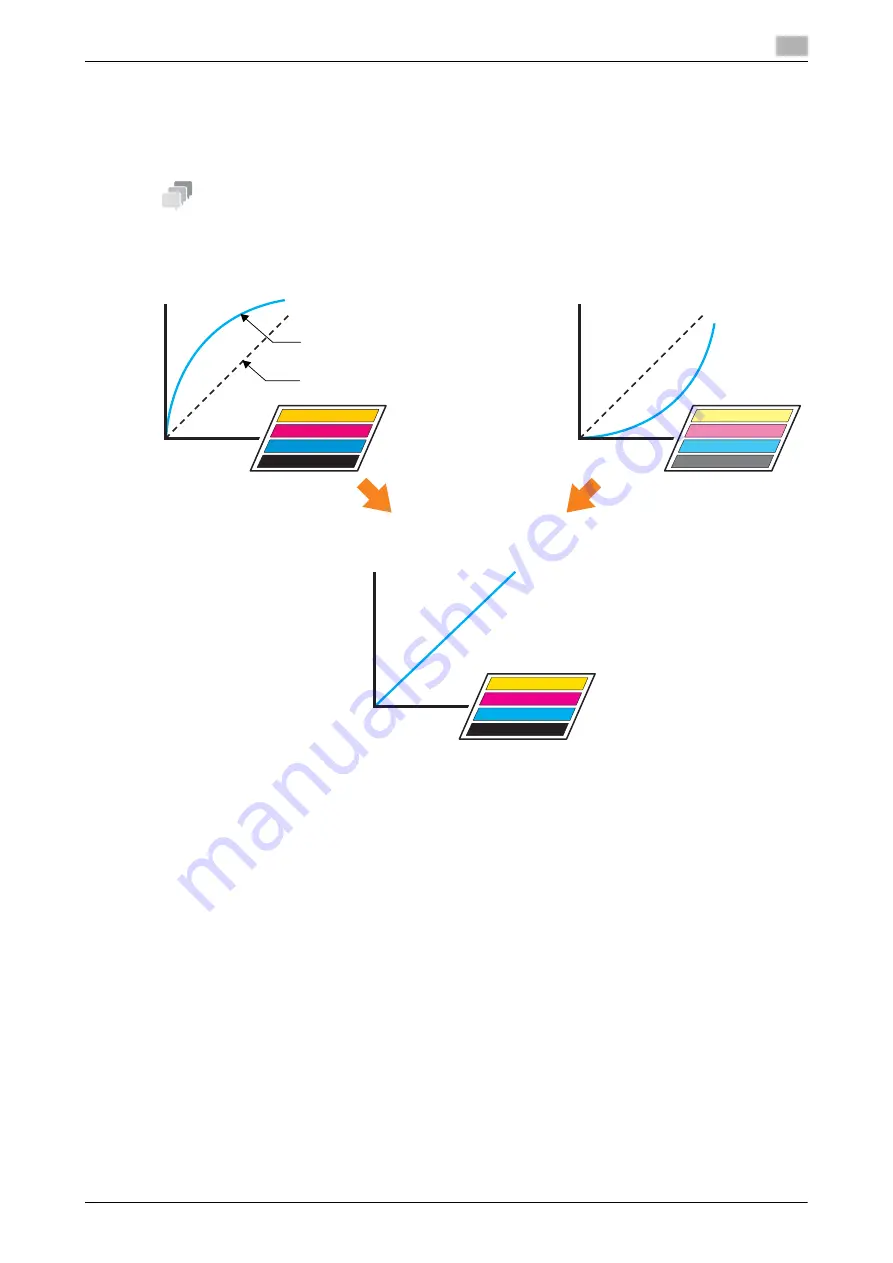
You can maintain the color image quality by executing calibration at the appropriate timing.

The reference value (target) of the entire printing system is registered in advance. Compare this reference val-
ue with the current measurement value to adjust the difference, and correct the printing density.

Tips

The reference image quality must be specified before carrying out daily quality management. Before this pro-
cessing, adjust the reference image quality (page 6-40).

Adjust the printing density to the reference value

Consistent printing result

When print density is high

When print density is low

Current measurement value

Reference value of target

Ou

tp

u

t (

%

)

Ou

tp

u

t (

%

)

Ou

tp

u

t (%)

Input (%)

Input (%)

Input (%)

Summary of Contents for AccurioPress C2060

Page 1: ...AccurioPress C2070 C2070P C2060 AccurioPrint C2060L Colour production printing system Quick GUIDE ...

Page 2: ......

Page 3: ...ons Image Controller IC 417 Image Controller IC 313 2 14 3 Let s Make Prints 3 1 Printing Flow 3 3 3 1 1 Step 1 Prepare the printer driver and applications 3 3 3 1 2 Step 2 Load paper into a tray 3 3 3 1 3 Step 3 Configure information of the paper loaded into a tray in this machine 3 3 3 1 4 Step 4 Use the printer driver to print data 3 4 3 1 5 Step 5 Check the finishing 3 4 4 Installing Software ...

Page 4: ...tment 6 3 6 1 2 Adjustment flow 6 3 6 1 3 Making the Both Sides Adjustment for each tray 6 4 6 2 Image Quality Adjustment 6 26 6 2 1 Image Quality adjustment 6 26 6 2 2 Daily image quality management Calibration 6 27 6 2 3 Maximum Density Auto Adjustment RU 6 29 6 2 4 Color Density Control 6 32 6 2 5 Executing calibration using the image controller 6 37 6 2 6 Specifying the reference image quality...

Page 5: ... 8 13 8 3 3 Step 3 Prepare the operating environment for SMB transmission 8 13 8 3 4 Step 4 Configure settings according to your environment 8 13 8 3 5 Step 5 Send scan data to a public folder 8 14 8 4 Major Specifications 8 15 8 4 1 Machine 8 15 8 4 2 Feeding related optional devices 8 16 8 4 3 Output related optional devices 8 22 8 4 4 Feeding and output related optional device 8 41 8 4 5 Electr...

Page 6: ...Contents 4 AccurioPress C2070series ...

Page 7: ...1 Introduction ...

Page 8: ......

Page 9: ...the instructions may lead to mishandling that may cause injury or property damage NOTICE This symbol indicates a risk that may result in damage to this machine or originals Follow the instructions to avoid property damage Tips This symbol indicates information that complements the topic or optional devices required to use a certain function dReference This symbol indicates a function or functions ...

Page 10: ...neral national and company safety provisions are observed 1 3 2 Impermissible operating conditions The system may not be operated if Errors or damage have been discovered Maintenance intervals have been exceeded Mechanical or electrical functions do not work as they should 1 3 3 Exclusion of liability The manufacturer of the system assumes no liability for damages if the system was operated under ...

Page 11: ...The HTML User s Guide uses JavaScript for the page display or search function Note that some of the functions may not work normally depending on your system environment Please be forewarned Problems may be able to be solved by using the latest Web browser Display resolution 1 024 e 768 pixels or more Title of manual in User s Guide DVD Overview Quick Guide This Guide This guide describes the basic...

Page 12: ...ress C2070 AccurioPress C2070P AccurioPress C2060 AccurioPrint C2060L This machine Indicates the entire system including options and functions The main body Indicates the main unit that provides print functions in this machine The machine Indicates a mechanical part related to the struc ture or mechanism AccurioPress C2070P Printer model Microsoft Windows Windows Product name Conventions used in t...

Page 13: ...Perfect Binder PB 503 Punch Kit PK 513 Saddle Stitcher SD 506 Punch Kit PK 522 Saddle Stitcher SD 510 Relay Unit RU 509 Saddle Stitcher SD 513 Relay Unit RU 510 Large Capacity Stacker Handcart LC 501 Output Tray OT 511 Large Capacity Stacker LS 506 Output Tray OT 510 Folding Unit FD 503 Multi Punch GP 501 Folding Unit FD 504 Auto Ring Binder GP 502 Feeding related optional devices Paper Feeder Uni...

Page 14: ...ons To check network information print out the Configuration Page Print Printing out the Configuration Page Print Image Controller IC 603 From the MACHINE screen on the touch panel select Controller Report Type Network Setting then press Execute Note down the IP address printed on the Configuration Page Print in the entry field according to your environment Sample IP address IPv4 address entry fie...

Page 15: ... Print in the entry field according to your environment Tips If necessary note down other network information in the following table To check network information the administrator privilege may be required Contact your machine ad ministrator NOTICE Some notes may include confidential information Handle this guide with great care In particular do not enter information such as the password Item Entr...

Page 16: ...1 10 AccurioPress C2070series Make a Note about This Machine Information 1 1 6 ...

Page 17: ...2 Before Getting Started ...

Page 18: ......

Page 19: ... on 1 Open the front door of the main body then turn the main power switch on When the main power switch is turned on the Power LED on the control panel lights up in orange 2 Turn on the sub power switch on the upper right corner of the main body When the sub power switch is turned on the Power LED on the control panel lights up in blue After the start screen has been displayed the default screen ...

Page 20: ...s the button on the top of the power switch For Image Controller IC 313 turn the power switch in the rear side on then press the power button in the front side NOTICE After this machine has started completely turn the image con troller on Tips If Machine is warming up is displayed on the MACHINE screen it indicates that this machine is in the warm up state Warm up processing takes approximately 6 ...

Page 21: ...ease do not turn the main power off 2 Turn off the main power switch NOTICE When turning the main power switch off then on be sure to wait for 10 seconds or longer before turning the main power switch on again If the main power switch is turned on again within 10 seconds the machine may not function normally Turning the power off Image Controller IC 417 1 On the MACHINE screen press Controller 2 P...

Page 22: ... turn off the sub power switch The touch panel display goes off and the Power LED on the control panel is changed from blue to orange 10 Turn off the main power switch NOTICE When turning the main power switch off then on be sure to wait for 10 seconds or longer before turning the main power switch on again If the main power switch is turned on again within 10 seconds the machine may not function ...

Page 23: ...ed off automatically Power off in progress Please do not turn the main power off 2 Turn off the main power switch NOTICE When turning the main power switch off then on be sure to wait for 10 seconds or longer before turning the main power switch on again If the main power switch is turned on again within 10 seconds the machine may not function normally 3 Press the Menu button on the control panel ...

Page 24: ...time periods available 5 min 10 min 15 min 30 min 60 min 90 min 120 min and 240 min from which you can select the desired one Power saving time periods 90 min 120 min and 240 min may not be displayed depending on regions Auto Shut OFF Turns off all LEDs except Power Save LED and Power LED on the control panel to reduce the power consumption of this machine This machine is placed into the Auto Shut...

Page 25: ... Guide NOTICE If this machine is turned off because the Weekly Timer has started job data is not received even if it is sent While this machine can be used normally send job data again ErP Setting Turns the main power off after the Auto Low Power mode Auto Shut OFF mode or the sub power switch is kept in the off state for the specified period of time There are seven power saving time periods avail...

Page 26: ...can print data on this machine via the printer driver using the application software installed on your com puter You can configure a layout or finish setting by implementing a simple action when printing data Copy functions You can specify conditions such as the original scan setting paper size or the finish setting to copy data More originals can be scanned in a short time by mounting an optional...

Page 27: ...ller In addition you can give a scan instruction from a computer on the network to import the scan data to your computer Tips Sending to a WebDAV server and saving to a USB flash drive are functions available only when Image Controller IC 603 is installed on this machine Scan functions are not available in the Printer model Hold function of print jobs using the HDD You can temporarily save an exec...

Page 28: ... via the network using the Web browser of the computer to check the status of this machine or configure various settings remotely from PageScope Web Connection Image Controller IC 417 Image Controller IC 313 WebTools WebTools is a device control utility program provided by the HTTP server built in to the Image Controller You can access the Image Controller via the network using the Web browser of ...

Page 29: ...b management function Job Centro Job Centro is an application that enables job management of this machine Using this function you can execute a print or copy job monitor a scan job operate and edit jobs temporarily saved on this machine and edit pages In addition you can acquire device information such as printer status consumable information or tray information to check the status of this machine...

Page 30: ...ab provides the functions for the job operator You can check the job status that is being processed by the controller or that is being printed and check an overview of the processed job You can also search or print a job calibrate the controller for stable color reproduction or check the log data Device control function The Device Center tab provides the functions for the administrator You can che...

Page 31: ... Scan Fiery Remote Scan is an application that is used to perform remote scanning to import a file from the E mail box and save it on the computer or to import scanned data into the application to edit it For details about how to use this application refer to the User s Guide supplied with the Fiery Color Server Fiery Hot Folders Fiery Hot Folders is an application that is used to set attributes t...

Page 32: ...2 2 Available Operations in this Machine 2 AccurioPress C2070series 2 16 ...

Page 33: ...3 Let s Make Prints ...

Page 34: ......

Page 35: ...have no original data 3 1 1 Step 1 Prepare the printer driver and applications Install the printer driver and applications in your computer After installation is completed configure information of the mounted devices using the printer driver to use optional functions For details refer to the following pages To install the printer driver Refer to page 4 7 To install applications Refer to page 4 11 ...

Page 36: ... 313 Click Quick Access tab then select the paper size in Document size In Paper tray you can select a tray to load paper to be printed into For information about other functions of the printer driver refer to page 5 16 4 Click Print Original data is printed and printed sheets are output to the output tray of this machine You can save print jobs on the HDD of this machine If print jobs are saved o...

Page 37: ...4 Installing Software ...

Page 38: ......

Page 39: ...Server 2008 R2 Windows Server 2012 Windows Server 2012 R2 CPU Any processor of the same or higher specifications as recommended for your operating system Memory Memory capacity as recommended for your operating system The memory must have a sufficient free space to support the operating sys tem and required applications Drive CD or DVD drive Item Specifications Operating System Mac OS X 10 7 10 8 ...

Page 40: ... If the installer does not start open the printer driver folder on the Driver CD DVD double click Au toRun exe then proceed to the procedure 2 2 Select Printer Install then select PS Plugin Driver 3 Select EN When the User Account Control window is displayed click Continue or Yes 4 Click Next 5 Enter the printer name or IP address then click Next The printer is created using the Ipr port To connec...

Page 41: ...to acquire device option information check the network setting 4 Click OK The device option information setting is then completed 4 1 4 In a Macintosh environment Installation Install the printer driver on your computer from the Driver CD DVD supplied with this machine then add the desired printer to the computer This guide describes how to install the PS Plug in driver in a Mac OS X 10 10 environ...

Page 42: ... To check the printer name of this machine select Utility Counter Administrator Setting Net work Setting NIC Settings Bonjour Setting 11 Click Add 12 Configure optional information of this machine then click OK or Continue Then configure the default setting for the printer driver For details refer to page 4 6 Default setting Check that optional information of this machine is configured correctly o...

Page 43: ...2 Windows Server 2012 R2 CPU Any processor of the same or higher specifications as recommended for your operating system Memory Memory capacity as recommended for your operating system The memory must have a sufficient free space to support the operating sys tem and required applications Drive DVD drive Item Specifications Operating System Mac OS X 10 7 10 8 10 9 10 10 10 11 CPU Intel Processor Me...

Page 44: ... button then click Control Panel Hardware and Sound View devices and printers In Windows Vista Server 2008 open the Start menu select Control Panel Hardware and Sound then click Printers 3 Click Add Printer In Windows Vista click Add a printer In Windows Server 2008 double click Add Printer 4 Click Add a local printer In Windows 8 1 Server 2012 Server 2012 R2 select The printer that I want isn t l...

Page 45: ...ave failed to acquire optional information check the network setting 4 Click OK The optional information setting of the machine is then completed 4 2 4 In a Macintosh environment Installation Install the printer driver on your computer from the User Software DVD supplied with this machine then add the desired printer to the computer This guide describes how to install the PostScript3 driver in a M...

Page 46: ...he Bonjour connected printer to be added in the Name list Specifying a printer displays the appropriate printer driver in the Use field If the printer driver is not displayed correctly select Select Printer Software then directly specify the desired printer driver To check the printer name of this machine select Administrator Setting Network Setting NIC Settings Bonjour Setting 16 Click Add Option...

Page 47: ... to support the operating sys tem and required applications Display 1 024 e 768 pixels or more Drive CD DVD ROM drive Network environment The TCP IP protocol setting must be configured correctly Item Specifications Operating System Windows Vista Windows 7 Windows 8 1 Windows 10 Windows Server 2008 Windows Server 2008 R2 Windows Server 2012 Windows Server 2012 R2 CPU Intel Core2 Duo 3 GHz or higher...

Page 48: ...rint density for in put density of each color of CMYK 3 Color Configuration Management Manages a set of various settings for color printing You can register and edit a color configuration and a profile set 4 Color Default Settings This function specifies default of color conversion You can manually specify default of color settings for RGB CMYK and others 5 Spot Color Adjusts an output color for a...

Page 49: ...lder and then click Next To change the destination folder click Change and then specify another folder 7 Click Install 8 Click Finish Start To start Color Centro first connect to this machine 0 Color Centro is a Java application If Java applications are blocked by a firewall permit network con nections for the Java applications 0 To connect Color Centro you need to specify the IP address and port ...

Page 50: ...while viewing page thumbnails or insert a chapter sep arator If necessary you can combine multiple jobs into a new job In the right hand pane of the page you can display jobs that are being processed or temporarily saved on this machine You can perform job operations such as output reprint change of the print priority or job de letion Checking device information In the left hand pane the device in...

Page 51: ...hange the destination folder click Change and then specify another folder 7 Click Install 8 Click Finish Start To start Job Centro first connect to this machine 0 Job Centro is a Java application If Java applications are blocked by a firewall permit network connec tions for the Java applications 0 To connect Job Centro you need to specify the IP address and port number of this machine Default port...

Page 52: ...stem The memory must have sufficient free space to support the operating system and applications Display 1 024 e 768 pixels or more Drive DVD drive Network environment The TCP IP protocol setting must be configured correctly Fiery Utility Description Fiery Command Work Station Manages jobs and image controller via the network Fiery Printer Delete Utility Completely deletes the printer driver from ...

Page 53: ...ayed click Continue or Yes 2 Click Next 3 Check the license agreement click I accept the terms of the license agreement then click Next 4 Check the destination folder To change the destination folder click Browse to specify the desired folder 5 Select a language then click Next 6 Select the check box of the software to be installed then click Next 7 Confirm the program folder name then click Next ...

Page 54: ... setting for displaying the icon on the desktop may be disabled Check whether or not the desktop display setting is disabled in Preferences of the Finder 2 Copy the Fiery Applications dmg file to the desktop then double click it The Disk Image file opens 3 Double click the Fiery Command Workstation file The installer starts For Fiery Remote Scan double click Fiery Remote Scan For Fiery Hot Folders...

Page 55: ...eges then enter the password For user privileges you can select the following items Administrator Can perform all operations Operator Can only perform job operations Guest Can view information only The default password is Fiery 1 If Operator or Guest is selected for user privileges you do not need to enter the password 5 Click Login Fiery Command WorkStation starts Starting Fiery Remote Scan To st...

Page 56: ...a Server 2008 R2 Server 2008 open the Start menu then click All Programs Fiery Fiery Hot Folders In Windows 8 Server 2012 click Fiery Hot Folders on the Start screen In Windows 8 1 Server 2012 R2 on the Start window click then click All Apps Fiery Hot Folders In Windows 10 click the Start button then click All apps Fiery Hot Folders In Macintosh select Go menu Applications Fiery Hot Folders then d...

Page 57: ...5 Basic Operations ...

Page 58: ......

Page 59: ...e sure to pull out the tray fully until a blue label shows on the rear left side of the tray Otherwise the feed roller may not open or another machine trouble may occur 2 Open the feed roller 3 Turn two side guide lock knobs in the front and rear sides counterclockwise to loosen them 4 While pressing the side guide lock release lever slide it to any position Slide both the front and rear side guid...

Page 60: ... sheets 80 g m2 21 lb Bond into Tray 1 and more than 1 000 sheets 80 g m2 21 lb Bond into Tray 2 Also do not load paper above the mark that indicates the height limit on the side guide plate Other wise a paper jam may occur Be sure that the rear guide plate is securely pressed against the paper If there is any gap between the rear guide plate and the paper this machine will not be able to detect t...

Page 61: ...ock wise to loosen them 3 While pressing the side guide lock release lever slide the side guide plates to any positions Determine their locations based on the size indicator of the bottom plate of the tray NOTICE To slide the side guide plates be sure to hold both side guide plates together If you move it by holding only either of the side guide plate the side guide plate that held may become disp...

Page 62: ...aper with the print side facing up 8 Close the tray Push the tray in until it locks into place The amount indicator changes from to in the tray information display area of the MA CHINE or COPY screen NOTICE Carefully close the tray Otherwise the machine may be subjected to an unexpected impact due to the tray or paper weight which may lead to a machine error 5 1 3 Loading Paper in Post Inserter of...

Page 63: ... paper loaded into a paper tray If standard size paper is loaded its size is recognized automatically To load custom size paper specify the required size 1 Press Paper Setting on the MACHINE screen You can also press Paper Setting on the COPY screen to specify the required size 2 Select the tray with paper loaded then press Change Set 3 Press Paper Type to select the desired paper type ...

Page 64: ...5 2 Paper Setting 5 AccurioPress C2070series 5 8 4 Press Paper Size 5 Select one of the options under Size Setting to fit the paper loaded into the tray ...

Page 65: ...hat the machine cannot distin guish in the operation of size detection To identify these sizes as one size so that they can be judged by the machine you can select the size to be detected in Detect Size Setting Custom Specify the value in items 1 to 3 You can name and register the size specified in Size Registration To recall the registered size select Size Recall Item 3 is not displayed depending...

Page 66: ...pecify the paper size and the number of tabs 7 If you select Detect Size Setting in Standard press OK This returns to the Size Setting screen This step is not required if you select Cus tom or Tab Paper 8 Press OK This returns to the Change Individual Set screen ...

Page 67: ... you press Paper Setting on the COPY screen to specify the paper size the screen re turns to the COPY screen Paper setting is then completed Tips For details about setting items refer to the HTML User s Guide To register paper conditions in a paper profile press Register OK on the Change Individual Set screen For details about how to register a paper profile refer to the HTML User s Guide ...

Page 68: ...the printer driver This guide shows a procedure example to make prints using the PS Plug in driver from Adobe Reader XI in the Windows 7 environment Color Mode Output Color Click Color Mode in the Printing Preferences window of the printer driver For Output Color select Auto Color Full Color or Gray Scale If Auto Color is selected the image controller automatically specifies the output color to fi...

Page 69: ...xt box on the right hand side of the selected color You can specify each of four colors accordingly For Example you can replace only one color with a corpo rate color or one color of 2 color printing with a spot color Use example Replace magenta and cyan with the respective spot colors special colors Tips A spot color name is indicated by prefix color name For example if the prefix is set to DIC a...

Page 70: ... other color set ting information You can only specify one Color Configuration at the time of printing to easily apply the color setting available for all paper types This is convenient when registering Color Configurations matching various conditions in the image controller dReference To manage Color Configuration select Color Configuration Management in Color Centro For details refer to the HTML...

Page 71: ... for example specifying an RGB or CMYK color conversion profile specifying a printer profile appropriate to the required paper type or se lecting a Tone Curve This function is convenient to temporarily apply a special color conversion setting dReference To register the default in the manual settings select Color Default Settings in Color Centro For details refer to the HTML User s Guide ...

Page 72: ...to specify the color mode using the printer driver Color mode Select an output color Open Color in the Print Setting screen of the printer driver then select Color mode from CMYK or Gray scale dReference Before selecting the color mode execute calibration For details refer to page 6 39 The color mode can also be specified in Color Setup of Fiery Command WorkStation For details refer to the User s ...

Page 73: ... basic defaults for color processing open Color in the Printing Preferences window then click Basic Settings You can also change the setting for each print job dReference You also select Color Setup of Fiery Command WorkStation to configure Basic Settings in the color mode For details refer to the User s Guide supplied with the Fiery Color Server ...

Page 74: ...to all items for color processing open Color in the Printing Preferences window then click Expert Settings You can also change the setting for each print job dReference You can also select Color Setup of Fiery Command WorkStation to configure Expert Settings in the color mode For details refer to the User s Guide supplied with the Fiery Color Server ...

Page 75: ...6 Maintaining the Finishing Quality ...

Page 76: ......

Page 77: ...ormation about how to enter from Both Sides refer to the HTML User s Guide 6 1 2 Adjustment flow Follow the procedure below to proceed the Both Sides Adjustment 1 Check the reference position of the print side To judge whether a print position is misaligned the required reference position adjustment must be completed on this machine Before starting the Both Sides Adjustment check the adjustment va...

Page 78: ...ou can identify from which paper tray the charts are printed out depending on the number of marks For details refer to the HTML User s Guide You can change the default screen of the Both Sides Adjust screen For more information contact your service representative In Printer model you cannot set the Scan Meas adjustment screen to the default 6 1 3 Making the Both Sides Adjustment for each tray Adju...

Page 79: ... which can be produced when mul tiple sheets are output Performing the Scan Meas adjustment may require readjustment of the Zoom and Image Shift Adjustment registered in a paper profile The Scan Meas adjustment is a simple method to adjust only the magnification ratio and image position of the back side To adjust both front and back sides perform the Chart Adjustment page 6 16 or Zoom and Image Sh...

Page 80: ...OTICE Use paper of A3 or larger or 11 e 17 or larger to output the background sheet When you press Output Background Sheet to display the PRINT MODE Screen for the background sheet the tray selected in step 2 is automatically se lected on the screen but it can be changed as desired Select a tray loaded with A3 or larger or 11 e 17 or larger paper You can also change the print count but only one sh...

Page 81: ...t 20 or more adjustment charts however only up to 20 adjustment charts can be scan measured continuously 9 Press Start on the control panel Adjustment charts are printed on both sides of the paper in the tray you selected in Step 2 10 Press Exit Print Mode 11 Press 2 Scan Adjustment Chart The Scan Adjustment Chart screen is dis played ...

Page 82: ... cm away from the vertical size guide and horizontal size guide respectively on the Original Glass making sure that the left and top sides are parallel to the vertical size guide and horizontal size guide respectively 13 Place the background sheet on the Original Glass then close the ADF Place the black side of the background sheet facing down facing the original glass then set it flush with the v...

Page 83: ...ext the measure ment may not be performed properly If the ADF is open scanning fails and a message is displayed Close the ADF then press Close in the message dialog box If scanning fails a message may be dis played Follow the on screen instructions to correctly place the adjustment chart and background sheet then press Close If you press Return on the Scan Adjustment Chart screen during scan measu...

Page 84: ... of the ad justment chart face up turned away from the original glass with its bottom edge po sitioned to the back side Third time Set the back side of the adjust ment chart face up turned away from the original glass with its top edge positioned to the back side Fourth time Set the back side of the adjust ment chart face up turned away from the original glass with its bottom edge posi tioned to t...

Page 85: ...ed by pressing Yes exceeds the available adjustment range a mes sage is displayed indicating that the available adjustment range has been exceeded Press Close to discard the adjustment value then retry scan measurement from the beginning Possible causes to exceed the adjustment range may include that the chart used in the scan meas urement is incorrect a different chart has been used the printing ...

Page 86: ...y enter adjustment values to adjust a gap This is convenient in order to adjust an unclear misalignment detected on the back side that occurs when performing duplex printing with a new type of paper or when paper in a tray has been changed NOTICE The Gap Adjustment is a simple method to adjust only the zoom ratio and image position of the back side To also adjust it on the front side carry out Cha...

Page 87: ...e of the printed out chart This figure shows an example to measure a The scale resolution is 0 5 mm In this figure the black line indicates the front side and the blue line indicates the back side The measurement value can be entered in units of up to 0 1 mm For example as shown in the figure if the scale of a is misaligned 1 5 mm in the plus side compared with the front side press 1 5 to enter 1 ...

Page 88: ...e If the printing position is misaligned to the plus side enter a negative value To reset a numeric value press Clear To switch the positive sign and negative sign press 9 When entry processing is completed press Adjustment Start The entered adjustment values are applied If Back Side Magnification Adjustment is set to OFF the value of d adjustment value of the transverse magnification Horizontal o...

Page 89: ...red 12 Press Exit Print Mode 13 After the adjustment is completed press OK To finely adjust the adjustment value continu ously proceed to step 4 in Zoom and Image Shift Adjustment page 6 22 To register adjustment values in a paper profile press Register OK For details about how to register a paper profile refer to the HTML User s Guide 14 Press Close to exit the adjustment Gap Adjustment is then c...

Page 90: ...adjustment Using this function you can only enter measurement values to carry out the both side adjustment This is convenient when an unclear misalignment is detected between the front and back sides to perform the du plex printing with a new type of paper or to change paper in a tray 1 Press Paper Setting on the MACHINE screen 2 Select the tray with the target paper loaded then press Change Set 3...

Page 91: ...es 6 17 6 1 Both Sides Adjustment 6 4 Select Front then press Chart Adjustment 5 Press Print Mode 6 When the PRINT MODE screen is displayed press Start on the control panel A test chart is printed out 7 Press Exit Print Mode ...

Page 92: ...tes an example to measure points 1 and 5 As illustrated in this example measure the line length at each printed point The measurement value can be entered in units of up to 0 1 mm Write down the measured lengths so that you do not forget them 9 Press each point number then enter the measured length using the keypad or on the screen To reset a value press Clear 1 5 7 6 8 2 3 4 1 5 ...

Page 93: ...When entry processing is completed press Adjustment Start In the next step adjust the back side 11 Select Back then press Chart Adjustment 12 Press Print Mode 13 When the PRINT MODE screen is displayed press Start on the control panel A test chart is printed out ...

Page 94: ...direction X axis and vertical direction Y axis The measurement value can be entered in units of up to 0 1 mm For example as shown in the figure if at point 1 is misaligned 2 0 mm in the plus side of the X direction and 1 5 mm in the minus side of the Y direction compared with the front side press 2 0 in the X direction to enter 2 0 as the adjustment value and press 1 5 in the Y direction to enter ...

Page 95: ... side enter a negative value To reset a value press Clear To switch the positive sign and negative sign press 17 When entry processing is completed press Adjustment Start 18 After the adjustment is completed press OK To finely adjust the adjustment value con tinuously proceed to step 4 in Zoom and Image Shift Adjustment page 6 22 To register the adjustment value in a paper profile press Register O...

Page 96: ...and right positions on the front and back sides Using this function can directly enter the adjustment value in percentage or with the required value This is convenient when you want to carry out fine adjustment after the Scan Measurement Adjustment the Gap Adjustment or the chart adjustment or you have the duplex printing result 1 Press Paper Setting on the MACHINE screen 2 Select the tray with th...

Page 97: ... 1 step basis Adjustment Range Vertical 1 00 to 1 00 Horizontal 1 00 to 1 00 Horizontal of Back must be specified between 0 80 and 0 20 To move the print side upward downward leftward or rightward image shift press Up Down or Right Left then enter the value To move the print side upward or rightward enter the value with a positive mark To move the print side downward or leftward enter the value wi...

Page 98: ...he mark to set the adjustment value to 1 00 The image on the back side is reduced by 1 In this figure the black mark indicates the front side and the blue mark indicates the back side Image shift adjustment example The image on the back side is misaligned 0 5 mm downward and 0 3 mm rightward com pared with that on the front side Press Up Down of Back then press 5 to set the adjustment value to 0 5...

Page 99: ...a paper profile refer to the HTML User s Guide 7 Press Close to exit the adjustment Zoom and Image Shift Adjustment is then com pleted Tips If printing positions are misaligned between the front and back sides even after the Both Sides Adjust ment has been carried out several times readjust the reference position on the print side For details about the adjustment procedure refer to the HTML User s...

Page 100: ... methods to adjust image quality To manage the daily image quality Carry out the density adjustment that is typically referred to as calibration Two methods are available To use an optional Relay Unit RU 509 and to use a colorimeter and applications supplied with the image controller For details refer to page 6 27 To specify the reference image quality Execute this method at the time of installati...

Page 101: ... reference val ue with the current measurement value to adjust the difference and correct the printing density Tips The reference image quality must be specified before carrying out daily quality management Before this pro cessing adjust the reference image quality page 6 40 Adjust the printing density to the reference value Consistent printing result When print density is high When print density ...

Page 102: ...es the color reproducibility that fluctu ates from day to day Color Density Control Select Basic Setting then set Periodical Adj Execution to ON If necessary execute Color Density Manual Control Order Menu item Description Without Relay Unit RU 509 With Relay Unit RU 509 STEP1 Gamma Automat ic Adj Refer to the HTML User s Guide Color Density Con trol Refer to the right hand section Gamma Automatic...

Page 103: ...tive Carry out Maximum Density Auto Adjustment RU using the paper that is used to register the target maximum density value target density When Maximum Density Auto Adjustment RU is performed image stabilization control is carried out if you return to the normal screen After image stabilization control is completed you must carry out calibration using the image controller Then carry out Color Dens...

Page 104: ...lity Adjustment 3 Press Max Density Auto Adj RU 4 Press Print Mode 5 Load the paper that has been used to register the target density into the tray The paper profile of the tray is automatically switched to the paper profile that has been used to register the target density ...

Page 105: ... Return to return to the Process Adjustment Menu screen Note that the tray remains set to the paper profile that has been used to register the target density Tips If Maximum Density Auto Adjustment RU is carried out the paper profile of the tray that has been used for auto adjustment is switched to the paper profile that has been used to register the target den sity and it is not returned to the p...

Page 106: ...this ma chine automatically executes calibration at periodic intervals Calibration is executed every arbitrarily specified number of sheets and you can keep printing using the ap propriate density Tips The printed chart is included in the print count Auto setting of Color Density Control 1 Press Adjustment on the MACHINE screen 2 Press Quality Adjustment 3 Press Color Density Control ...

Page 107: ...e Job Start Chart Tray Setting OFF 6 Press Next 7 Specify each item as follows Switch Color 1st or 2nd Precise Adjustment Interval OFF Select Switch Color 1st or 2nd depending on conditions To ensure the quality Pre cise is appropriate Adjustment Interval allows you to specify the number of output sheets which is avail able until readjustment mode is specified For details refer to the HTML User s ...

Page 108: ...series 6 34 8 Press OK 9 Press Close 10 Press Exit ADJUSTMENT Automatic Adjustment is set A chart is printed out periodically and calibra tion is carried out automatically Tips Selecting Color Density Manual Control can carry out the manual adjustment ...

Page 109: ... Color Density Manual Control 1 Press Adjustment on the MACHINE screen 2 Press Quality Adjustment 3 Press Color Density Control 4 Press Color Density Manual Control This function is available only when Use Color Density Control is set to ON in Color Density Control Basic Setting ...

Page 110: ...6 2 Image Quality Adjustment 6 AccurioPress C2070series 6 36 5 Press Print Mode 6 Press Quality Adj 7 Press of Screen Pattern to select a screen 8 Press Close ...

Page 111: ...ty Control to OFF For information about the setting procedure refer to page 6 32 5 Select Instrument on the Settings menu then select FD 5BT FD 7 M0 6 Click Settings in 1 Paper Type Screen Settings 7 Select Paper Type and Screen Settings required for calibration then click OK 8 Click Start Calibration 9 Click Print 10 Select the paper tray required to print out a chart then click Print A chart is ...

Page 112: ... refer to the manual supplied with this ma chine 17 Likewise measure rows D to A The measured parts are color displayed on the screen in the same way as for the chart 18 When the measurement is completed click Register Unregistered calibration data is erased when Color Centro is closed 19 When the message is displayed click OK 20 Check the calibration data measurement result using the graph displa...

Page 113: ...ample Specify a printing environment according to the paper and tray actually used 5 Click Continue A chart is printed out in a matter of time after this machine started running 6 Click OK 7 Securely place EFI Spectrometer ES 1000 in the calibration cradle then click Continue 8 Load the measurement page on the measurement guide plate 9 Follow the instructions on the measurement screen to measure c...

Page 114: ...estart then execute Step 4 Calibration without Relay Unit RU 509 or Step 4 Color Density Control with Relay Unit RU 509 installed in sequence If sufficient adjustment results are not obtained via daily maintenance also carry out the adjustment in this order For details about the setting procedure refer to the HTML User s Guide Order Menu item Description Without Relay Unit RU 509 With Relay Unit R...

Page 115: ...ls about the setting procedure refer to the HTML User s Guide Order Menu item Description Without Relay Unit RU 509 With Relay Unit RU 509 STEP1 Screen Pattern Refer to the HTML User s Guide Select the screen to be used with the screen setting assignment changed STEP2 Gamma Automatic Adj Refer to the HTML User s Guide Automatically adjusts the color reproducibility of all the output paper STEP3 Pr...

Page 116: ...pening the screen to be adjusted When the finisher or saddle stitcher is mounted on this machine you can finely adjust various functions such as fold positions or staple positions dReference For details about how to adjust the finisher refer to the HTML User s Guide 1 Press Adjustment on the MACHINE screen 2 Press Finisher Adjustment ...

Page 117: ...r Adjustment Adjusts stapler operations such as staple positioning Setting item Description Staple Finisher Adjustment Adjusts stapler operations such as staple positioning Multi Folder Adjustment Adjusts multi folder operations such as punch positioning or fold positioning Stacker Adjustment Adjusts stacker operations such as paper width or paper length adjustment Saddle Stitcher Adjustment Adjus...

Page 118: ...nment be tween the fold and the staples Half Fold Stopper Adj Adjusts the half fold stopper position Punch Adjustment Adjusts punch positions Tri Fold Adjustment Adjusts tri folding positions 2 Pos Staple Pitch Adj Adjusts the staple pitch Post Inserter Tray Size Adjusts the tray size of the post inserter Output Quantity Limit Sets the maximum number of pages to be printed ...

Page 119: ...7 Troubleshooting ...

Page 120: ......

Page 121: ...avoid inhaling it or even getting skin contact If toner lands on your skin or clothing wash thoroughly with soap and water If you inhale toner move to a place with fresh air and gargle with a lot of water repeatedly Should you get symptoms such as coughing seek medical advice If you get toner into your eyes immediately rinse them with running water for over 15 minutes Seek medical advice if irrita...

Page 122: ...help message If you press the yellow row in the Consum able and Scrap Indicators display area of the touch panel the window shown in step 3 is displayed directly 2 Press Consumable Scrap 3 Follow the on screen instructions to replace a toner bottle The number on the right hand side of the help message indicates a replacement procedure To dis play the next step press Attach the cap of a new toner b...

Page 123: ...ators display dReference The following describes how to replace a staple cartridge in the left hand side stapler of the Saddle Stitch er SD 506 For information about how to replace staple cartridges refer to the HTML User s Guide 1 Press on the upper right corner of the touch panel or Help on the control panel to display the help message If you press the yellow row in the Consum able and Scrap Ind...

Page 124: ...ge indicates a replacement procedure To dis play the next step press NOTICE The Saddle Stitcher SD 506 contains two staple cartridges Check the message then be sure to pull out the empty cartridge To remove a staple cartridge securely hold its right and left sides and pull it out toward you To install a staple cartridge be careful not to mistake the top side for the bottom side If the top side is ...

Page 125: ...sage Waste toner box is full Please replace the box is displayed on the MACHINE screen and the Waste Toner Box indicator changes to yellow in the Con sumable and Scrap Indicators display 1 Press on the upper right corner of the touch panel or Help on the control panel to display the help message If you press the yellow row in the Consum able and Scrap Indicators display area of the touch panel the...

Page 126: ...curioPress C2070series 7 8 3 Press the Waste Toner tab then follow the on screen instructions to replace the waste toner box The number on the right hand side of the help message indicates a replacement procedure To dis play the next step press ...

Page 127: ...n then follow the guidance to clear a paper jam Do not turn off the main power switch while clearing a paper jam Otherwise the trays or conveyance fixing unit cannot be pulled out JAM Position screen If a paper jam occurs the JAM Position screen is displayed and the position of the paper jam is indi cated by a number Tips Pressing Close changes to the MACHINE screen Even while the MACHINE screen i...

Page 128: ...uidance so you can clear a paper jam while checking each step 1 Press Illustration on the JAM Position screen 2 Check the displayed contents then remove jammed paper If the description spans multiple pages Next is displayed Pressing Next can check the next step Pressing JAM Position returns to the JAM Po sition screen 3 Follow the guidance to remove jammed paper Pressing Next can check the next st...

Page 129: ...s not dis played on the touch panel again In particular check the following points Check whether a slip of paper is left on the back of the part indicated by the number on the touch panel If you cannot smoothly remove jammed paper do not remove it forcibly Contact your service representative Open and close the door of the part indicated by the number on the touch panel again This operation may cle...

Page 130: ...n To address this problem load the specified paper into a tray or you can forcibly print on the currently loaded paper of a different size If you use Image Controller IC 417 Image Controller IC 313 and enable Job Mismatch Confirm Details may not be displayed on the touch panel In this case see page 7 15 Replacing with the specified paper 1 Press Confirm Details on the MACHINE screen 2 Select a tra...

Page 131: ...AccurioPress C2070series 7 13 7 3 If the Specified Paper is not Found 7 4 Replace paper into the tray then press Close 5 Press Start on the control panel Printing starts using the selected tray ...

Page 132: ...oPress C2070series 7 14 Forcibly printing using the loaded paper 1 Press Confirm Details on the MACHINE screen 2 Select a tray with print paper loaded then press Forced Output 3 Press Start on the control panel Printing starts using the selected tray ...

Page 133: ...ntroller IC 313 1 Press Controller on the MACHINE screen 2 Press Login 3 Select Administrator or Operator enter the password then press Login If you select Operator you do not need to enter the password 4 Select the print job 5 Press the tray in which print sheets are loaded Printing starts using the selected tray ...

Page 134: ...HTML User s Guide 3 Click Device Information and then click Option 4 Check Remain in HDD Pre RIP Form Scan Data To delete unnecessary scan data use an HDD TWAIN driver For details refer to the user s guide for the HDD TWAIN driver Automatically delete scan data that are stored in the HDD image controller area after the specified time period has elapsed For details refer to the HTML User s Guide Fo...

Page 135: ...olor image quality dReference For details refer to page 6 40 After specifying the reference image quality you can execute calibration at periodic intervals to maintain the image quality dReference If you have changed the screen or paper make the advanced adjustment For details refer to the HTML Us er s Guide 7 6 Image Position Adjustment The previously adjusted image position may be misaligned by ...

Page 136: ...7 7 If you forget the administrator password 7 AccurioPress C2070series 7 18 ...

Page 137: ...8 Appendix ...

Page 138: ......

Page 139: ... a search keyword into the search field then click Search Tips For functions on which you refer to the HTML User s Guide in this guide enter the function name or setting item into the entry field then click Search you can search for the target explanation 2 Confirm the setting required for the target finishing in an operation exam ple The HTML User s Guide contains various procedure examples for e...

Page 140: ...board and mouse This port is available for low power devices only Provide an external supply of power for devices that require a large amount of power 4 Touch panel Displays a screen such as the MACHINE screen to enable you to carry out machine operations and settings Also operation or troubleshooting procedures can be provided 5 Control panel Performs operations or configures settings 6 Toner sup...

Page 141: ...ase T Connect a network cable to use this machine as a network printer or scanner 16 Image Controller IC 417 This is the installation position when Image Controller IC 417 is equipped Required to use this machine as a printer or scanner 17 Image Controller IC 313 This is the server when Image Controller IC 313 is equipped Required to use this machine as a printer or scanner 18 Row selection button...

Page 142: ...s 8 6 22 Down button Scrolls the screen downward 23 Menu button Display the menu screen 24 Up button Scrolls the screen upward 25 Control panel Restarts Image Controller IC 313 displays its IP address and carries out reboot processing No Name Description ...

Page 143: ...power switch off in usual operation 2 Toner access door Open when adding toner 3 Toner bottle cover Y M C K Open when placing a toner bottle in the machine Toner bottles are classified into four colors yellow Y magenta M cyan C and black K 4 Drum unit Generates a print image 5 Conveyance fixing unit Pulled out to remove jammed paper For information about how to handle levers and knobs of the conve...

Page 144: ...ur service representative 7CAUTION DO NOT pull out the toner bottle other than the time to exchange for running out of toner If you pull out the toner bottle in which the toner remains an area nearby may become dirty with toner 6 Lever M1 Locks the conveyance fixing unit If a paper jam has been detected push this lever down to the left and pull out the conveyance fixing unit 7 Fixing unit Fuses to...

Page 145: ...Data LED Flashes when receiving a job 5 Interrupt Used to make an interrupt copy Using this function you can interrupt the currently execut ed job to prioritize a copy job when you want to make a copy on urgent business The Interrupt LED flashes until interrupt becomes possible When interrupt becomes pos sible the Interrupt LED lights up 6 Stop Stops machine operations or erases the scanned image ...

Page 146: ...he details of the specified print job 13 Utility Counter Displays the UTILITY screen and various counters 14 Mode Memory Registers conditions of the target copy or scan function or recalls the registered conditions Also you can recall the previous conditions 15 Accessibility Adjusts the time for which a response is returned when you pressed a key or button on the touch panel or control panel 16 He...

Page 147: ... E mail attachment send it to a shared computer SMB server the FTP server or the WebDAV server or save it to the USB flash drive installed on this machine This section describes the function Scan to SMB to send data to the SMB server Scan to SMB is a function that converts the original data scanned on this machine to a computer compatible file and sends the converted data to a target computer or a...

Page 148: ... type in set user and press the Enter key The domain name and user name are displayed The login user name is shown following USERNAME The user name is required to specify a destination Write down the user name so that you do not forget it 3 Enable file sharing In Windows 7 8 1 10 select Control Panel Network and Internet Network and Sharing Center Change advanced sharing settings then click Turn o...

Page 149: ...ettings For details refer to the HTML User s Guide For Image Controller IC 417 or Image Controller IC 313 to configure the network settings select WebTools Configure Launch Configure Network For details refer to the user s guide supplied with Fiery Color Server 8 3 3 Step 3 Prepare the operating environment for SMB transmission Enable the SMB transmission function Set SMB Send Setting of this mach...

Page 150: ...older Send scan data to a public folder of the registered SMB server In the SCAN screen of this machine select an SMB destination configure the scan conditions then press Start dReference You can specify conditions such as the image quality and scanning size For details about scan conditions refer to the HTML User s Guide ...

Page 151: ...c Tab Paper 62 g m2 to 256 g m2 16 lb Bond to 68 lb Bond Coated GL ML GO MO 81 g m2 to 256 g m2 22 lb Bond to 68 lb Bond Paper size Tray 1 upper tray A3 w B4 w SRA4 w v A4 w v B5 w v A5 w 11 e 17 w 9 e 11 v 8 5 e 14 w 8 5 e 11 w v 5 5 e 8 5 w 8K w 16K w v Foolscap Tab Paper A4T v 8 5 e 11T v Custom Width 139 7 mm to 330 2 mm Length 182 mm to 431 8 mm Width 5 5 to 12 98 Length 7 17 to 17 Tray 2 low...

Page 152: ...11 w v 5 5 e 8 5 w 8K w 16K w v Tab Paper A4T v 8 5 e 11T v Custom Width 100 mm to 330 2 mm Length 182 mm to 487 7 mm Width 3 94 to 13 Length 7 17 to 19 2 Tray 4 lower tray SRA3 w A3 w B4 w SRA4 w v A4 w v B5 w v A5 w v B6 w A6 w 13 e 19 w 12 e 18 w 11 e 17 w 8 5 e 14 w 8 5 e 11 w v 5 5 e 8 5 w 8K w 16K w v Tab Paper A4T v 8 5 e 11T v Custom Width 100 mm to 330 2 mm Length 148 mm to 487 7 mm Width...

Page 153: ...00 mm to 330 2 mm Length 139 7 mm to 487 7 mm Width 3 94 to 13 Length 5 5 to 19 2 JIS standard sizes are used for B series in the factory setting For JIS ISO switching contact your service representative You can change the detectable standard size Also you can select ON from K Size on the Utility Counter screen to detect the K size For details refer to the HTML User s Guide If the paper width is l...

Page 154: ...K size For details refer to the HTML User s Guide Storage capacity 2 500 sheets 80 g m2 21 lb Bond Paper tray Specifications Paper weight 64 g m2 to 300 g m2 17 lb Bond to 81 lb Bond Coated paper 81 g m2 to 300 g m2 22 lb Bond to 81 lb Bond Paper size SRA3 w A3 w B4 w SRA4 w v A4 w v B5 v 13 e 19 w 11 e 17 w 9 e 11 w 12 e 18 w 8 5 e 14 w 8 5 e 11 w v 8K w 16K v Tab Paper A4T v 8 5 e 11T v Custom W...

Page 155: ...to 330 2 mm Length 148 mm to 487 7 mm Width 3 94 to 13 Length 5 83 to 19 2 JIS standard sizes are used for B series in the factory setting For JIS ISO switching contact your service representative You can change the detectable standard size Also you can select ON from K Size on the Utility Counter screen to detect the K size For details refer to the HTML User s Guide Foolscap refers to 8 5 e 13 w ...

Page 156: ...ails refer to the HTML User s Guide Paper tray 1 Upper tray 2 Lower tray Specifications Paper weight 50 g m2 to 300 g m2 13 lb Bond to 81 lb Bond Paper size SRA3 w A3 w B4 w SRA4 w v A4 w v B5 w v A5 v 13 e 19 w 12 e 18 w 11 e 17 w 8 5 e 14 w 8 5 e 11 w v 7 25 e 10 5 w v 5 5 e 8 5 v 8K w 16K w v Foolscap Tab Paper A4T v 8 5 e 11T v Custom Width 182 mm to 331 mm Length 139 mm to 483 mm Width 7 17 t...

Page 157: ...ide Paper tray 1 Upper tray 2 Lower tray Specifications Paper weight 50 g m2 to 300 g m2 13 lb Bond to 81 lb Bond Paper size Upper tray A4 w v B5 w v A5 v 8 5 e 11 w v 7 25 e 10 5 w 5 5 e 8 5 v 16K w v Custom Width 182 mm to 330 0 mm Length 139 mm to 297 mm Width 7 17 to 12 99 Length 5 47 to 11 69 Lower tray A3 w B4 w SRA4 w A4 w v B5 w v A5 v 12 e 18 w 11 e 17 w 8 5 e 14 w 8 5 e 11 w v 7 25 e 10 ...

Page 158: ...ical or humidifier curl adjustment The humidifier curl adjustment requires an optional Humidifier HM 102 Color Density Control Paper weight 40 g m2 to 350 g m2 11 lb Bond to 93 lb Bond Paper size SRA3 w A3 w B4 w SRA4 w v A4 w v B5 w v A5 w v B6 w A6 w 13 e 19 w 12 e 18 w 11 e 17 w 8 5 e 14 w 9 e 11 v 8 5 e 11 w v 7 25 e 10 5 w v 5 5 e 8 5 w v 8K w 16K w v Fools cap Tab Paper A4T v 8 5 e 11T v Cus...

Page 159: ...ght 40 g m2 to 350 g m2 11 lb Bond to 93 lb Bond Paper size SRA3 w A3 w B4 w SRA4 w v A4 w v B5 w v A5 w v A6 w 13 e 19 w 12 e 18 w 11 e 17 w 8 5 e 14 w 9 e 11 v 8 5 e 11 w v 5 5 e 8 5 w v 8K w 16K w v Foolscap Tab Paper A4T v 8 5 e 11T v Custom Width 95 mm to 331 mm Length 133 mm to 488 mm Width 3 74 to 13 03 Length 5 24 to 19 21 Foolscap refers to 8 5 e 13 w 8 25 e 13 w 8 12 e 13 25 w or 8 e 13 ...

Page 160: ... 10 5 w v 16K w v 1 500 sheets 80 g m2 21 lb Bond SRA3 w A3 w B4 w SRA4 w v 13 e 19 w 12 e 18 w 11 e 17 w 8 5 e 14 w 8K w Foolscap 500 sheets 80 g m2 21 lb Bond A5 w v B6 w 5 5 e 8 5 w v Multi folder tray 200 sheets Foolscap refers to 8 5 e 13 w 8 25 e 13 w 8 12 e 13 25 w or 8 e 13 w Specifications Half Fold Tri Fold in Tri Fold out Z Fold Gate Double Parallel Fold Paper weight Primary main tray H...

Page 161: ... to the number of sheets loadable in the main tray for straight delivery Output tray 1 Stacker tray 2 Secondary sub tray Specifications Function Stacker tray with carriage Sort output group output Offset output enabled Paper weight Stacker tray 50 g m2 to 350 g m2 13 lb Bond to 93 lb Bond Secondary sub tray 40 g m2 to 350 g m2 11 lb Bond to 93 lb Bond Paper size Stacker tray SRA3 w A3 w B4 w SRA4 ...

Page 162: ...3 lb Bond 136 g m2 to 176 g m2 36 lb Bond to 46 lb Bond 15 sheets or 14 sheets 1 sheet 200 g m2 53 lb Bond 177 g m2 to 216 g m2 47 lb Bond to 57 lb Bond 10 sheets 217 g m2 to 256 g m2 58 lb Bond to 68 lb Bond 5 sheets Specifications Multi Half Fold Multi Tri Fold Paper weight Multi Half Fold 50 g m2 to 244 g m2 13 lb Bond to 65 lb Bond Multi Tri Fold 50 g m2 to 91 g m2 13 lb Bond to 24 lb Bond Pap...

Page 163: ...A3 w B4 w SRA4 w A4 w B5 w 12 e 18 w 11 e 17 w 8 5 e 14 w 8 5 e 11 w 7 25 e 10 5 w 8K w 16K w Fools cap Custom Width 120 mm to 331 mm Length 257 mm to 488 mm Width 4 72 to 13 03 Length 10 12 to 19 21 Wide paper Foolscap refers to 8 5 e 13 w 8 25 e 13 w 8 12 e 13 25 w or 8 e 13 w Sheet volume Maximum number of stapled and folded sheets No cover paper 62 g m2 to 80 g m2 16 lb Bond to 21 lb Bond 35 f...

Page 164: ...lb Bond to 24 lb Bond 3 sheets Tri Fold with crease Multi Fold released 106 g m2 to 216 g m2 29 lb Bond to 57 lb Bond 1 sheets Specifications Trim Paper weight 50 g m2 to 300 g m2 13 lb Bond to 81 lb Bond Paper size SRA3 w A3 w B4 w SRA4 w A4 w B5 w 12 e 18 w 11 e 17 w 8 5 e 14 w 8 5 e 11 w 7 25 e 10 5 w 8K w 16K w Fools cap Custom Width 120 mm to 331 mm Length 257 mm to 488 mm Width 4 72 to 13 03...

Page 165: ...tions Fold Staple Spine Corner Forming Paper weight 50 g m2 to 216 g m2 13 lb Bond to 57 lb Bond Paper size SRA3 w A3 w B4 w SRA4 w A4 w B5 w 12 e 18 w 11 e 17 w 8 5 e 14 w 8 5 e 11 w 7 25 e 10 5 w 8K w 16K w Fools cap Custom Width 120 mm to 331 mm Length 257 mm to 488 mm Width 4 72 to 13 03 Length 10 12 to 19 21 Foolscap refers to 8 5 e 13 w 8 25 e 13 w 8 12 e 13 25 w or 8 e 13 w Minimum quantity...

Page 166: ... to 307 mm Length 279 mm to 472 mm Width 5 47 to 12 09 Length 10 98 to 18 58 Secondary sub tray SRA3 w A3 w B4 w SRA4 w v A4 w v B5 w v A5 w v B6 w A6 w 13 e 19 w 12 e 18 w 11 e 17 w 9 e 11 v 8 5 e 14 w 8 5 e 11 w v 7 25 e 10 5 w v 5 5 e 8 5 w v 8K w 16K w v Fools cap Tab Paper A4T v 8 5 e 11T v Custom Width 95 mm to 331 mm Length 139 mm to 488 mm Width 3 74 to 13 03 Length 5 47 to 19 21 Foolscap ...

Page 167: ...6 w A6 w 13 e 19 w 12 e 18 w 11 e 17 w 8 5 e 14 w 8 5 e 11 w v 7 25 e 10 5 w v 5 5 e 8 5 w v 8K w 16K w v Foolscap Tab Paper A4T v 8 5 e 11T v Custom Width 100 mm to 331 mm Length 139 mm to 488 mm Width 3 94 to 13 01 Length 5 47 to 19 21 Foolscap refers to 8 5 e 13 w 8 25 e 13 w 8 12 e 13 25 w or 8 e 13 w Sheet volume Primary main tray 3 000 sheets 80 g m2 21 lb Bond A4 w v B5 w v 8 5 e 11 w v 7 2...

Page 168: ... 15 Number of stored copies 100 sets 2 to 9 sheets stapled Paper length 150 mm to 417 mm 5 9 to 16 42 50 sets 2 to 9 sheets stapled Paper length Other than the above 50 sets 10 to 20 sheets stapled 30 sets 21 to 30 sheets stapled 25 sets 31 to 40 sheets stapled 20 sets 41 to 50 sheets stapled Specifications Punch with Punch Kit PK 512 or PK 513 installed Number of punch holes Punch Kit PK 512 Metr...

Page 169: ...dth 95 mm to 331 mm Length 133 mm to 488 mm Width 3 74 to 13 03 Length 5 24 to 19 21 Secondary sub tray SRA3 w A3 w B4 w SRA4 w v A4 w v B5 w v A5 w v 12 e 18 w 11 e 17 w 9 e 11 v 8 5 e 14 w 8 5 e 11 w v 7 25 e 10 5 w v 5 5 e 8 5 v 8K w 16K w v Foolscap Tab Paper A4T v 8 5 e 11T v Custom Width 95 mm to 331 mm Length 133 mm to 488 mm Width 3 74 to 13 03 Length 5 24 to 19 21 Foolscap refers to 8 5 e...

Page 170: ...ze SRA3 w A3 w B4 w SRA4 w v A4 w v B5 v A5 v 13 e 19 w 12 e 18 w 11 e 17 w 9 e 11 v 8 5 e 14 w 8 5 e 11 w v 7 25 e 10 5 v 5 5 e 8 5 v 8K w 16K v Foolscap Tab Paper A4T v 8 5 e 11T v Custom Width 203 mm to 331 mm Length 139 mm to 488 mm Width 7 99 to 13 03 Length 5 47 to 19 21 Foolscap refers to 8 5 e 13 w 8 25 e 13 w 8 12 e 13 25 w or 8 e 13 w ...

Page 171: ... g m2 13 lb Bond to 19 lb Bond 100 50 50 20 35 75 g m2 to 80 g m2 20 lb Bond to 21 lb Bond 100 50 30 30 30 35 81 g m2 to 91 g m2 22 lb Bond to 24 lb Bond 60 50 30 30 30 35 92 g m2 to 135 g m2 25 lb Bond to 35 lb Bond 50 50 30 30 30 30 136 g m2 to 176 g m2 36 lb Bond to 46 lb Bond 40 40 30 30 30 25 177 g m2 to 216 g m2 47 lb Bond to 57 lb Bond 25 25 25 25 25 20 217 g m2 to 256 g m2 58 lb Bond to 68...

Page 172: ... e 17 w 9 e 11 v 8 5 e 11 v 8K w 16K v Foolscap refers to 8 5 e 13 w 8 25 e 13 w 8 12 e 13 25 w or 8 e 13 w Specifications Fold Staple with Saddle Stitcher SD 510 installed Paper weight 50 g m2 to 216 g m2 13 lb Bond to 57 lb Bond Cover 50 g m2 to 300 g m2 13 lb Bond to 81 lb Bond Paper size A3 w B4 w A4 w 12 e 18 w 11 e 17 w 8 5 e 14 w 8 5 e 11 w 8K w Custom Width 120 mm to 331 mm Length 240 mm t...

Page 173: ... e 11 v 8 5 e 14 w 8 5 e 11 w v 7 25 e 10 5 w v 8K w 16K w v Foolscap Tab Paper A4T v 8 5 e 11T v Custom Width 182 mm to 320 mm Length 148 mm to 458 mm Width 7 17 to 12 60 Length 5 83 to 18 03 Size only for straight delivery A5 w B6 w 5 5 e 8 5 w v min 128 0 mm e 139 0 mm 5 04 e 5 47 Secondary sub tray SRA3 w A3 w B4 w SRA4 w v A4 w v B5 w v A5 w v B6 w A6 w 13 e 19 w 12 e 18 w 11 e 17 w 9 e 11 v ...

Page 174: ...m 0 22 or less Up to two sheets of 200 g m2 53 2 lb Bond can be inserted within the number of stapled sheets above Specifications Fold Staple Paper weight 60 g m2 to 105 g m2 16 lb Bond to 28 lb Bond Paper size SRA3 w A3 w B4 w SRA4 w A4 w 12 e 18 w 11 e 17 w 8 5 e 14 w 8 5 e 11 w 8K w Custom Width 210 mm to 320 mm Length 279 mm to 458 mm Width 8 27 to 12 60 Length 10 98 to 18 03 Sheet volume Numb...

Page 175: ...ction Punch The punch hole pattern varies according to the die set For details refer to the HTML User s Guide Specifications Function Bypass mode Transports paper without punch processing Punch mode Carries out punch processing through a punch path return path Die set model Metric area Die Set DS 508 509 510 511 512 513 514 515 516 517 518 Inch area Die Set DS 501 502 503 504 505 506 507 Paper wei...

Page 176: ...y 75 g m2 to 120 g m2 20 lb Bond to 32 lb BondCover 163 g m2 to 216 g m2 44 lb Bond to 57 lb BondTabbed paper 163 g m2 max 44 lb Bond max Book size sheets Smallest 5 body sheets 75 g m2 20 lb Bond 2 covers 216 g m2 57 lb Bond Largest 100 body sheets 75 g m2 20 lb Bond 2 covers 216 g m2 57 lb Bond Bypass sheet size weight Same as main body ...

Page 177: ...dth may not be correctly printed depending on the paper type or environment Banner paper weight 128 g m2 to 256 g m2 34 lb Bond to 68 lb Bond Feeding mode 1 sided only Face up output Straight output only Stack ca pacity Feeding ex tension tray 10 sheets Other than Coated paper 1 sheet for coated paper Output exten sion tray For details about the stack capacity of the output extension tray refer to...

Page 178: ...emory space 10 GB or more Shared with the main body Built in fonts European 136 fonts Page description lan guage Adobe PostScript3 3020 Specifications Function Built in image controller Capacity HDD capacity 500 GB Memory capacity 2 GB Built in fonts European 138 fonts Page description lan guage Adobe PostScript3 3020 Specifications Function External print server Capacity HDD capacity 1 TB Memory ...

Page 179: ...inal feeding Original type Simplex original 35 g m2 to 210 g m2 10 lb Bond to 57 lb Bond 35 g m2 to 49 g m2 10 lb Bond to 12 lb Bond is available in Thin Paper mode Duplex original 50 g m2 to 210 g m2 13 lb Bond to 57 lb Bond Original size Metric area A3 w B4 w A4 w v B5 w v A5 w v B6 w A6 w 11 e 17 w 8 5 e 11 w v 8 e 13 w Inch area A3 w B4 w A4 w v B5 w v 11 e 17 w 8 e 14 w 8 5 e 11 w v 5 5 e 8 5...

Page 180: ... weight is typically used in the machine setting To convert the paper weight to the ream weight for each format refer to the following list Paper weight g m2 lb Bond Duodecimo kg Standard size of series B kg Octavo kg Standard size of series A kg 62 to 74 16 to 19 53 51 0 37 34 0 63 61 5 44 40 5 75 to 80 20 to 21 64 62 0 45 41 0 69 66 5 47 44 0 81 to 91 22 to 24 70 67 0 48 44 5 78 75 5 54 50 0 92 ...

Page 181: ...tment and Glossy refer to the HTML User s Guide AccurioPress C2070 AccurioPress C2070P Temperature de tected by Humid ity Temperature Sensor Paper weight g m2 lb Bond 1 minute copying speed at 1 sided output with plain pa per A4 v 8 5 e 11 v Normal setting When Glossy is selected 17 C or higher 62 to 74 16 to 19 71 pages A4 v 70 pages 8 5 e 11 v 51 pages 75 to 80 20 to 21 81 to 91 22 to 24 92 to 1...

Page 182: ...C or higher 62 to 74 16 to 19 61 pages A4 v 60 pages 8 5 e 11 v 45 pages 75 to 80 20 to 21 81 to 91 22 to 24 92 to 105 25 to 28 106 to 135 29 to 36 136 to 176 37 to 47 177 to 216 48 to 57 45 pages 30 pages 217 to 256 58 to 68 257 to 300 69 to 81 30 pages Lower than 17 C 62 to 74 16 to 19 61 pages A4 v 60 pages 8 5 e 11 v 45 pages 75 to 80 20 to 21 81 to 91 22 to 24 45 pages 92 to 105 25 to 28 106 ...

Page 183: ...imposition printing When using the Tray 2 Main body lower tray When this machine is equipped with the Banner Tray Unit MK 740 Tips For information about other paper trays refer to the HTML User s Guide 487 7 mm 19 20 330 2 mm 13 Maximum printing area Crosswise direction 323 mm 12 72 Paper feed direction 480 mm 18 9 1 200 0 mm 47 24 330 2 mm 13 Maximum printing area Crosswise direction 323 mm 12 72...

Page 184: ...8 6 Maximum paper size and printing area 8 AccurioPress C2070series 8 48 ...

Reviews: