


401027/B
5
Dimensional surveying ..................................................................................................100
Alignment ......................................................................................................................101
Calibration .....................................................................................................................102
Vessel coordinate system ...............................................................................................102
CABLE LAYOUT AND INTERCONNECTIONS........................... 104
Read this first .................................................................................................................105
Cable plans.....................................................................................................................106
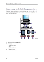
Cable plan, Processing Unit .................................................................................107
Cable plan, Transmitter Unit ................................................................................108
Cable plan, Receiver Unit, 0.5 degree.................................................................. 110
Topside cable plan ................................................................................................ 113
List of EM 712 cables .................................................................................................... 113
Transmit transducer cables............................................................................................. 119
Receive transducer cables ..............................................................................................123
Clock synchronization (1PPS) .......................................................................................127
External synchronization ...............................................................................................129
Hydrographic Work Station rear connectors (MP 5810) ...............................................132
Cable drawings and specifications .................................................................................134
RS-232 serial line using three wires and RJ45 connector ....................................135
RS-422 serial line using five wires and RJ45 connector ......................................136
Adapter for D-connector to RJ45 connector for RS-422 .....................................137
Clock synchronisation (1PPS) using a coax cable ...............................................138
External synchronisation ......................................................................................139
Remote control overview .....................................................................................140
Remote control .....................................................................................................142
Remote Control using K-Rem ..............................................................................143
Dummy plug for not using remote control ...........................................................144
Remote control of Transmitter Unit .....................................................................145
Remote control of Receiver Unit..........................................................................147
TECHNICAL SPECIFICATIONS.............................................. 151
Performance specifications ............................................................................................152
Interface specifications...................................................................................................154
Weight and outline dimensions ......................................................................................158
Power requirements .......................................................................................................160
Environmental requirements..........................................................................................161
Alignment specifications................................................................................................164
EQUIPMENT HANDLING ....................................................... 166
Transporting Kongsberg Maritime equipment...............................................................167
Lifting units and transportation boxes ...........................................................................168
Inspection of units and transportation boxes after arrival..............................................170
Installation manual
Summary of Contents for EM 712
Page 71: ...401027 B 71 216148 EM 712 Transducer TX1 dimensions Drawing file ...
Page 72: ...72 401027 B Kongsberg EM 712 Installation manual ...
Page 73: ...401027 B 73 221048 EM 712 Transducer TX2 dimensions Drawing file ...
Page 74: ...74 401027 B Kongsberg EM 712 Installation manual ...
Page 75: ...401027 B 75 219621 EM 712 Transducer RX1 dimensions Drawing file ...
Page 76: ...76 401027 B Kongsberg EM 712 Installation manual ...
Page 77: ...401027 B 77 216146 EM 712 Transducer RX2 dimensions Drawing file ...
Page 78: ...78 401027 B Kongsberg EM 712 Installation manual ...
Page 79: ...401027 B 79 223137 EM 712 Transducer mounting frame 0 5 degrees Drawing file ...
Page 80: ...80 401027 B Kongsberg EM 712 Installation manual ...
Page 81: ...401027 B 81 223139 EM 712 Transducer mounting frame 1 degree Drawing file ...
Page 82: ...82 401027 B Kongsberg EM 712 Installation manual ...
Page 83: ...401027 B 83 223273 EM 712 Transducer mounting frame 2 degrees Drawing file ...
Page 84: ...84 401027 B Kongsberg EM 712 Installation manual ...
Page 85: ...401027 B 85 317812 EM 712 Casing w mounting frame 0 5 degrees Drawing file ...
Page 87: ...401027 B 87 375817 EM 712 Combined casing w mounting frame 1 degree Drawing file ...
Page 89: ...401027 B 89 396402 EM 712 Transmitter Unit dimensions Drawing file ...
Page 91: ...401027 B 91 396428 EM 712 Receiver Unit dimensions Drawing file ...
Page 92: ...92 401027 B 385422 Processing Unit dimensions Kongsberg EM 712 Installation manual ...
Page 93: ...401027 B 93 378828 Hydrographic Work Station dimensions Drawing file ...
Page 94: ...94 401027 B Kongsberg EM 712 Installation manual ...
Page 95: ...401027 B 95 371591 Rack installation kit dimenisons Drawing file ...
Page 96: ...96 401027 B 370275 Remote Control Unit K REM dimensions Kongsberg EM 712 Installation manual ...
Page 97: ...401027 B 97 Drawing file ...
Page 163: ...401027 B 163 Certificates IEC 60945 IACS E10 Technical specifications ...
Page 177: ...401027 B 177 7 Observe the handling rules for transducers Equipment handling ...
Page 188: ... 2018 Kongsberg Maritime ...


