


54
401027/B
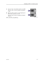
Observe the relevant instructions and safety information provided by the paint
manufacturer.
Rinse with fresh water
For non permanent installations, the transducer should be rinsed with fresh water every
time it is taken out of the water.
Painting the transducer face
Marine growth (biological fouling) on the transducer face reduces the EM 712
performance. We recommend that you paint the transducer face immediately after
installation, and then again as often as required to maintain the protection.
Prerequisites
The following tools and consumables are required.
• Personal protection
• Fresh water
• A mild synthetic detergent and a plastic brush
• Fine-grade sandpaper (240 inch grit size)
• Primer
• Anti-fouling paint
• Wet film gauge
• Airless spray
Because some paint types may be aggressive to the polyurethane in the transducer,
consult our list of approved paints.
Context
The transducer has not been designed with any protection against biological fouling.
Anti-fouling paint may therefore be applied to the transducer face.
To minimize the negative acoustical effects the layer of anti-fouling paint must be as
thin as possible.
Note
The anti-fouling paint will reduce the acoustical performance of the transducer.
The surface roughness of the transducer substrate and the thickness of the paint may
also influence the performance.
Kongsberg Maritime can not be held responsible for any negative consequences of the
anti-fouling paint.
Kongsberg EM 712 Installation manual
Summary of Contents for EM 712
Page 71: ...401027 B 71 216148 EM 712 Transducer TX1 dimensions Drawing file ...
Page 72: ...72 401027 B Kongsberg EM 712 Installation manual ...
Page 73: ...401027 B 73 221048 EM 712 Transducer TX2 dimensions Drawing file ...
Page 74: ...74 401027 B Kongsberg EM 712 Installation manual ...
Page 75: ...401027 B 75 219621 EM 712 Transducer RX1 dimensions Drawing file ...
Page 76: ...76 401027 B Kongsberg EM 712 Installation manual ...
Page 77: ...401027 B 77 216146 EM 712 Transducer RX2 dimensions Drawing file ...
Page 78: ...78 401027 B Kongsberg EM 712 Installation manual ...
Page 79: ...401027 B 79 223137 EM 712 Transducer mounting frame 0 5 degrees Drawing file ...
Page 80: ...80 401027 B Kongsberg EM 712 Installation manual ...
Page 81: ...401027 B 81 223139 EM 712 Transducer mounting frame 1 degree Drawing file ...
Page 82: ...82 401027 B Kongsberg EM 712 Installation manual ...
Page 83: ...401027 B 83 223273 EM 712 Transducer mounting frame 2 degrees Drawing file ...
Page 84: ...84 401027 B Kongsberg EM 712 Installation manual ...
Page 85: ...401027 B 85 317812 EM 712 Casing w mounting frame 0 5 degrees Drawing file ...
Page 87: ...401027 B 87 375817 EM 712 Combined casing w mounting frame 1 degree Drawing file ...
Page 89: ...401027 B 89 396402 EM 712 Transmitter Unit dimensions Drawing file ...
Page 91: ...401027 B 91 396428 EM 712 Receiver Unit dimensions Drawing file ...
Page 92: ...92 401027 B 385422 Processing Unit dimensions Kongsberg EM 712 Installation manual ...
Page 93: ...401027 B 93 378828 Hydrographic Work Station dimensions Drawing file ...
Page 94: ...94 401027 B Kongsberg EM 712 Installation manual ...
Page 95: ...401027 B 95 371591 Rack installation kit dimenisons Drawing file ...
Page 96: ...96 401027 B 370275 Remote Control Unit K REM dimensions Kongsberg EM 712 Installation manual ...
Page 97: ...401027 B 97 Drawing file ...
Page 163: ...401027 B 163 Certificates IEC 60945 IACS E10 Technical specifications ...
Page 177: ...401027 B 177 7 Observe the handling rules for transducers Equipment handling ...
Page 188: ... 2018 Kongsberg Maritime ...


