


40
401027/B
Procedure
1
Determine the physical location of the transducer.
Note
It is important to minimize the alongship gap between the receiver and tranceiver
arrays to improve the performance at very shallow water (to get overlap between
RX and TX footprints).
Make sure that all possible considerations are made to reduce noise.
For more information, see:
Where to install the transducer, page 20
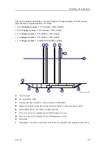
2
Determine the installation principle.
Several installation principles may be used. The principle must be chosen according
to the vessel’s hull design.
For more information, see:
Transducer installation principles, page 34
3
Prepare the transducer installation arrangement.
The installation arrangement must be capable of accepting the transducer frames.
We recommend that the frames are mounted into steel casings.
For more information, see:
Manufacturing and installing the casings, page 42
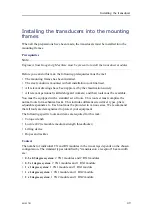
4
Prepare and install the necessary cable conduit from the top of the transducer to
the sonar room.
For more information, see:
Designing, manufacturing and mounting the steel
5
Install the mounting frames.
For more information, see:
Installing the mounting frames, page 47
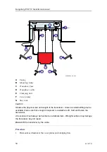
6
Install the transducer modules.
For more information, see:
Installing the transducers into the mounting frames,
7
Lay the transducer cables from the transducer modules to the steel conduits.
Each cable is marked in both ends with the module’s serial number and cable
number.
8
Pull the transducer cables up through the steel conduit and strap them to protect
against damage.
9
Seal the steel conduits.
Kongsberg EM 712 Installation manual
Summary of Contents for EM 712
Page 71: ...401027 B 71 216148 EM 712 Transducer TX1 dimensions Drawing file ...
Page 72: ...72 401027 B Kongsberg EM 712 Installation manual ...
Page 73: ...401027 B 73 221048 EM 712 Transducer TX2 dimensions Drawing file ...
Page 74: ...74 401027 B Kongsberg EM 712 Installation manual ...
Page 75: ...401027 B 75 219621 EM 712 Transducer RX1 dimensions Drawing file ...
Page 76: ...76 401027 B Kongsberg EM 712 Installation manual ...
Page 77: ...401027 B 77 216146 EM 712 Transducer RX2 dimensions Drawing file ...
Page 78: ...78 401027 B Kongsberg EM 712 Installation manual ...
Page 79: ...401027 B 79 223137 EM 712 Transducer mounting frame 0 5 degrees Drawing file ...
Page 80: ...80 401027 B Kongsberg EM 712 Installation manual ...
Page 81: ...401027 B 81 223139 EM 712 Transducer mounting frame 1 degree Drawing file ...
Page 82: ...82 401027 B Kongsberg EM 712 Installation manual ...
Page 83: ...401027 B 83 223273 EM 712 Transducer mounting frame 2 degrees Drawing file ...
Page 84: ...84 401027 B Kongsberg EM 712 Installation manual ...
Page 85: ...401027 B 85 317812 EM 712 Casing w mounting frame 0 5 degrees Drawing file ...
Page 87: ...401027 B 87 375817 EM 712 Combined casing w mounting frame 1 degree Drawing file ...
Page 89: ...401027 B 89 396402 EM 712 Transmitter Unit dimensions Drawing file ...
Page 91: ...401027 B 91 396428 EM 712 Receiver Unit dimensions Drawing file ...
Page 92: ...92 401027 B 385422 Processing Unit dimensions Kongsberg EM 712 Installation manual ...
Page 93: ...401027 B 93 378828 Hydrographic Work Station dimensions Drawing file ...
Page 94: ...94 401027 B Kongsberg EM 712 Installation manual ...
Page 95: ...401027 B 95 371591 Rack installation kit dimenisons Drawing file ...
Page 96: ...96 401027 B 370275 Remote Control Unit K REM dimensions Kongsberg EM 712 Installation manual ...
Page 97: ...401027 B 97 Drawing file ...
Page 163: ...401027 B 163 Certificates IEC 60945 IACS E10 Technical specifications ...
Page 177: ...401027 B 177 7 Observe the handling rules for transducers Equipment handling ...
Page 188: ... 2018 Kongsberg Maritime ...


