


401027/B
49
Installing the transducers into the mounting
frames
When all the preparations have been made, the transducers must be installed into the
mounting frames.
Prerequisites
Note
Engineers from Kongsberg Maritime must be present to install the transducer modules.
Before you can do this task, the following prerequisites must be met:
• The mounting frames has been installed.
• The steel conduit is mounted with all installation work finalized.
• All relevant drawings have been approved by the classification society.
• All relevant personnel (skilled shipyard workers) and their tools must be available.
You must be equipped with a standard set of tools. This tool set must comprise the
normal tools for mechanical tasks. This includes different screwdriver types, pliers,
adjustable spanners etc. Each tool must be provided in various sizes. We recommend
that all tools are demagnetized to protect your equipment.
The following specific tools and items are required for this task:
• Torque wrench
• Loctite 242 (removable medium strength threadlocker)
• Lifting device
• Ropes and tackles
Context
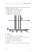
The number of individual TX and RX modules in the two arrays depends on the chosen
configuration. The standard types identified by "transmission x reception" beam width
are:
•
0.5 x 0.5 degrees system
: 2 TX1 modules and 2 RX 1modules
•
0.5 x 1 degree system
: 2 TX1 modules and 1 RX1 module
•
1 x 1 degree system
: 1 TX1 module and 1 RX1 module
•
1 x 2 degrees system
: 1 TX1 module and 1 RX2 module
•
2 x 2 degrees system
: 1 TX2 module and 1 RX2 module
Summary of Contents for EM 712
Page 71: ...401027 B 71 216148 EM 712 Transducer TX1 dimensions Drawing file ...
Page 72: ...72 401027 B Kongsberg EM 712 Installation manual ...
Page 73: ...401027 B 73 221048 EM 712 Transducer TX2 dimensions Drawing file ...
Page 74: ...74 401027 B Kongsberg EM 712 Installation manual ...
Page 75: ...401027 B 75 219621 EM 712 Transducer RX1 dimensions Drawing file ...
Page 76: ...76 401027 B Kongsberg EM 712 Installation manual ...
Page 77: ...401027 B 77 216146 EM 712 Transducer RX2 dimensions Drawing file ...
Page 78: ...78 401027 B Kongsberg EM 712 Installation manual ...
Page 79: ...401027 B 79 223137 EM 712 Transducer mounting frame 0 5 degrees Drawing file ...
Page 80: ...80 401027 B Kongsberg EM 712 Installation manual ...
Page 81: ...401027 B 81 223139 EM 712 Transducer mounting frame 1 degree Drawing file ...
Page 82: ...82 401027 B Kongsberg EM 712 Installation manual ...
Page 83: ...401027 B 83 223273 EM 712 Transducer mounting frame 2 degrees Drawing file ...
Page 84: ...84 401027 B Kongsberg EM 712 Installation manual ...
Page 85: ...401027 B 85 317812 EM 712 Casing w mounting frame 0 5 degrees Drawing file ...
Page 87: ...401027 B 87 375817 EM 712 Combined casing w mounting frame 1 degree Drawing file ...
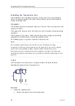
Page 89: ...401027 B 89 396402 EM 712 Transmitter Unit dimensions Drawing file ...
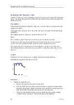
Page 91: ...401027 B 91 396428 EM 712 Receiver Unit dimensions Drawing file ...
Page 92: ...92 401027 B 385422 Processing Unit dimensions Kongsberg EM 712 Installation manual ...
Page 93: ...401027 B 93 378828 Hydrographic Work Station dimensions Drawing file ...
Page 94: ...94 401027 B Kongsberg EM 712 Installation manual ...
Page 95: ...401027 B 95 371591 Rack installation kit dimenisons Drawing file ...
Page 96: ...96 401027 B 370275 Remote Control Unit K REM dimensions Kongsberg EM 712 Installation manual ...
Page 97: ...401027 B 97 Drawing file ...
Page 163: ...401027 B 163 Certificates IEC 60945 IACS E10 Technical specifications ...
Page 177: ...401027 B 177 7 Observe the handling rules for transducers Equipment handling ...
Page 188: ... 2018 Kongsberg Maritime ...


