background image

PC130-7

20-229

TROUBLESHOOTING

CONNECTOR ARRANGEMENT DRAWING AND ELECTRIC

CIRCUIT DIAGRAM OF EACH SYSTEM

(1)

a

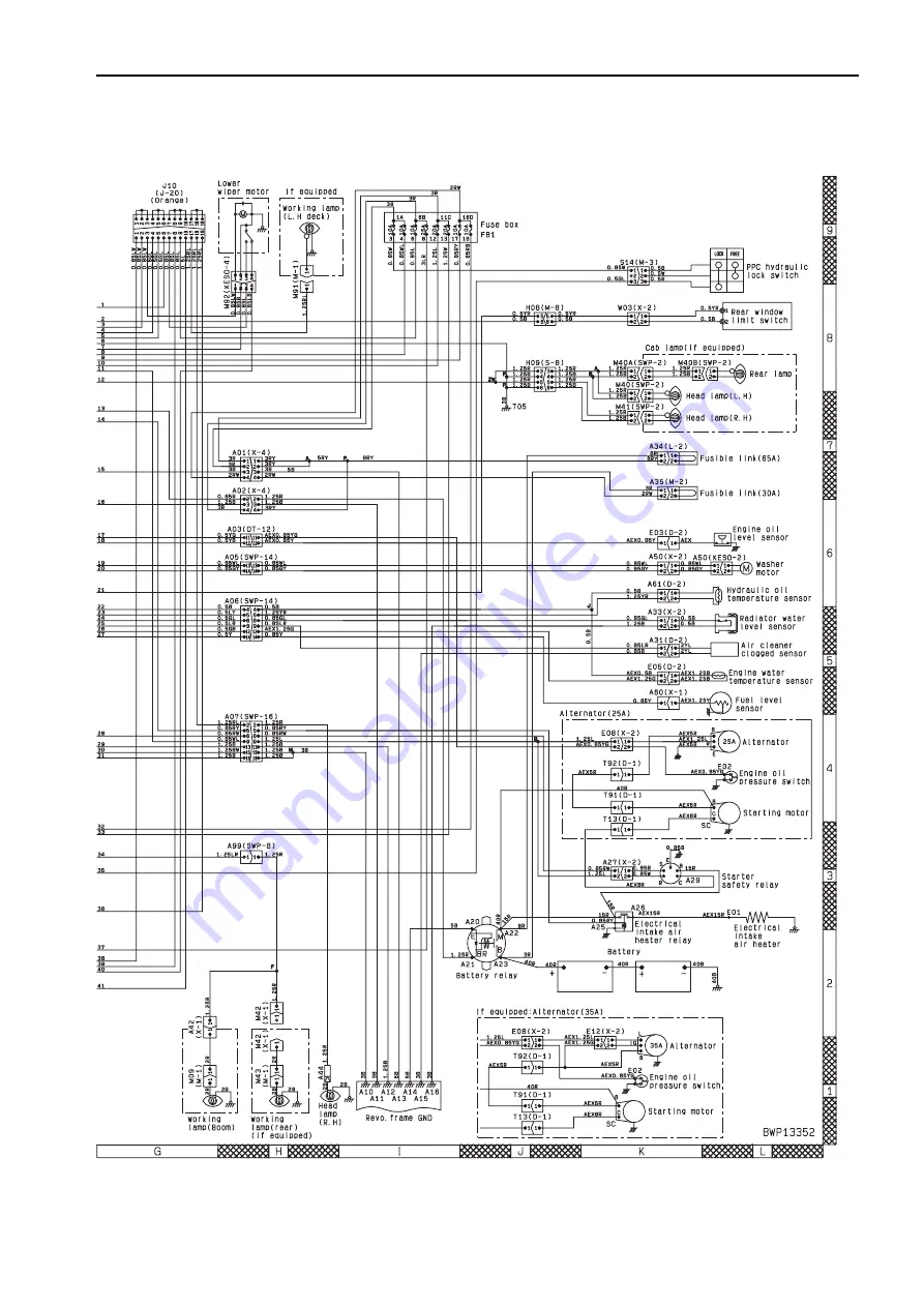
This circuit diagram is made by excerpting the monitor panel system, engine preheating/starting/charging
system, lower wiper system, and light system from the general electric circuit diagram.

Summary of Contents for PC130-7

Page 1: ...vailable in your area Please consult your local Komatsu distributor for those items you may require Materials and specifications are subject to change without notice PC130 7 mounts the SAA4D95LE 3 eng...

Page 2: ...2 PC130 7 CONTENTS No of page 01 GENERAL 01 1 10 STRUCTURE AND FUNCTION 10 1 20 TESTING AND ADJUSTING 20 1 30 DISASSEMBLY AND ASSEMBLY To be issued next time 40 MAINTENANCE STANDARD 40 1 90 OTHERS 90...

Page 3: ...5 10 36 10 37 10 38 10 39 10 40 10 41 10 42 10 43 10 44 10 45 10 46 Mark Page Revision number 10 47 10 48 10 49 10 50 10 51 10 52 10 53 10 54 10 55 10 56 10 57 10 58 10 59 10 60 10 61 10 62 10 64 10 6...

Page 4: ...Q 20 255 1 Q 20 256 1 Q 20 257 1 Q 20 258 1 Q 20 301 1 Q 20 302 1 Q 20 303 1 Q 20 304 1 Q 20 305 1 Q 20 306 1 Q 20 307 1 Q 20 308 1 Q 20 310 1 Q 20 311 1 Q 20 312 1 Q 20 313 1 Q 20 314 1 Q 20 315 1 Q...

Page 5: ...1 Q 20 610 1 Q 20 611 1 Q 20 612 1 Q 20 613 1 Q 20 614 1 Q 20 615 1 Q 20 616 1 Q 20 617 1 Q 20 618 1 Q 20 619 1 Q 20 620 1 Q 20 621 1 Q 20 622 1 Q 20 623 1 Mark Page Revision number Q 20 624 1 40 1 40...

Page 6: ......

Page 7: ...and the history of operation to judge if there is a failure 3 These standard values are not the standards used in dealing with claims When carrying out testing adjusting or troubleshooting park the ma...

Page 8: ...0 360 2 0 20 320 360 Blow by pressure Coolant temperature Within operating range At rated output kPa mmH2O Max 0 49 Max 50 0 98 100 Oil pressure Coolant temperature Within operating range MPa kg cm2 A...

Page 9: ...e IN 9 5 0 5 9 5 0 5 OUT 8 0 0 5 8 0 0 5 Bucket control valve 8 0 0 5 8 0 0 5 Swing control valve 8 0 0 5 8 0 0 5 Travel control valve 8 0 0 5 8 0 0 5 Control lever stroke Boom control lever Engine St...

Page 10: ...375 At power max 34 8 1 0 355 10 36 3 39 2 370 400 Bucket relief pressure At normal relief 31 9 325 33 3 36 8 340 375 At power max 34 8 1 0 355 10 36 3 39 2 370 400 Swing relief pressure 28 9 1 5 295...

Page 11: ...lic oil temperature 45 55 C Engine speed High idling Working mode A Time taken to swing 90 and 180 after starting 90 sec 2 9 0 3 Max 3 5 180 4 0 0 4 Max 8 5 Time taken to swing Hydraulic oil temperatu...

Page 12: ...igh idling Working mode A Measure time taken to rotate track shoe 5 turns after 1 turn Lo sec 46 1 9 2 46 1 9 2 Hi 21 9 2 2 23 1 3 0 Travel speed Actual travel Hydraulic oil temperature 45 55 C Engine...

Page 13: ...tip Hydraulic oil temperature 45 55 C Level and flat place Bucket Full of dirt and sand or filled with rated load 1 080 kg Level boom top retract arm cylinder fully and extract bucket cylinder fully E...

Page 14: ...nts of cushion CURL sec 3 2 0 4 Max 4 4 DUMP 3 1 0 3 Max 3 7 Bucket speed Hydraulic oil temperature 45 55 C Engine speed High idling Working mode A Measure time taken to move bucket between DUMP strok...

Page 15: ...from DUMP stroke end and measure time taken to start mov ing bucket again after it is stopped For measuring posture see WORK EQUIPMENT 7 sec Max 2 0 Max 3 0 Oil leakage Cylinder Hydraulic oil tempera...

Page 16: ...nd starting swinging Hydraulic oil temperature 45 55 C Engine High idling Working mode A Bucket Filled with rated load Hard and level place Set arm vertically and lower back of bucket to ground Raise...

Page 17: ...r becomes large at that point a When measuring without removing the pump from the machine if the engine speed cannot be set to the speci fied speed with the fuel control dial calculate the pump discha...

Page 18: ......

Page 19: ...TING AND ADJUSTING OIL PRESSURE IN WORK EQUIPMENT SWING AND TRAVEL CIRCUITS 20 122 MEASURING CONTROL CIRCUIT BASIC PRESSURE 20 125 TESTING AND ADJUSTING OIL PRESSURE IN PUMP PC CONTROL CIRCUIT 20 126...

Page 20: ...99 401 2320 Hydraulic tester 1 Pressure gauge 0 98MPa 10kg cm2 3 799 401 3500 Adapter 1 Size 06 4 799 101 5220 Nipple 1 Size 10 x 1 25mm 07002 11023 O ring 1 Measuring fuel injection timing F 1 795 10...

Page 21: ...pressure M 1 799 101 5002 Hydraulic tester 1 Same as E1 790 261 1203 Digital hydraulic tester 1 2 799 401 3100 Adapter 1 Size 03 Measuring PPC valve out put pressure N 1 799 101 5002 Hydraulic tester...

Page 22: ...Set the fuel control dial in the high idling MAX position 2 Relieve the arm circuit by moving the arm IN and measure the engine speed 4 Measuring pump relief and one touch power maximizing speed 1 Set...

Page 23: ...ed scale 6 After finishing measurement remove the measuring instrument and return the removed parts 2 Measuring with smoke meter A2 1 Insert probe 1 of smoke meter A2 in the outlet of exhaust pipe 1 a...

Page 24: ...of smoke meter A2 and collect the exhaust gas into the filter paper 8 Place the contaminated filter paper on the clean filter paper at least 10 sheets in the filter paper holder and read the indicated...

Page 25: ...pression top dead center In this case rotate the crankshaft one more turn 4 While the No 1 cylinder is at the compression top dead center adjust the valve clearances marked with q in the valve arrange...

Page 26: ...p dead center adjust the valve clearances marked with Q in the valve arrangement draw ing a Adjust the valve clearance according to step 4 above 7 After finishing adjustment return the removed parts 3...

Page 27: ...the adapter a Secure the adapter with the clamping holder and mounting bolt for the nozzle holder 3 Mounting bolt 39 2 49 Nm 4 5 kgm 6 Remove governor spring 2 7 Put governor lever 3 of the fuel inje...

Page 28: ...sprocket and track frame to lock the travel mechanism securely 4 Start the engine and warm it up to the operating range Engine coolant temperature Within operat ing range Hydraulic oil temperature 45...

Page 29: ...ulic tester E2 4 Start the engine and heighten the engine coolant temperature to the operating range 5 Measure the oil pressure during low idling and high idling 6 After finishing measurement remove t...

Page 30: ...er arm of the No 1 cylinder can be moved by the valve clearance with the hand If the rocker arm cannot be moved the No 1 cylinder is not at the compression top dead center In this case rotate the cran...

Page 31: ...Y DELIVERY VALVE METHOD a After repairing or replacing the fuel injection pump or timing gear adjust the injection timing according to the following procedure ADJUSTING a Apply the delivery valve meth...

Page 32: ...e stem of No 1 air intake valve 11 and set it to the 0 point a Since the No 1 cylinder is at the compres sion top dead center set this point as the 0 point 9 Rotate the crankshaft about 45 in reverse...

Page 33: ...ry valve holder 14 and then tighten the mounting nuts tempo rarily a The position where fuel stops flowing out of the No 1 delivery valve holder is the position to start fuel injection in the No 1 cyl...

Page 34: ...Screw in sensor 1 until its tip touches the tooth tip of flywheel ring gear 2 2 Threads Gasket sealant LG 6 2 Return sensor 1 by the specified angle a Returning angle of sensor 1 1 6 turn a After this...

Page 35: ...adjust it according to the following procedure 1 Loosen alternator mounting bolts 1 and 2 2 Adjust the belt tension by moving alternator 5 with adjustment bolt 4 a Turn the adjusting belt to left the...

Page 36: ...ust it according to the following procedure 1 Loosen compressor bracket mounting bolts 1 and 2 2 Adjust the belt tension by moving compressor 3 and bracket 4 together a Use a bar etc to move the brack...

Page 37: ...p to the height of the revolving frame bottom a At this time the front end of the upper struc ture lowers and the rear end rises 3 Set the dial gauge G to the 0 point 4 Set the arm at almost a right a...

Page 38: ...wing proce dure 1 When tension is too high 1 Loosen valve 1 gradually to discharge the grease k Since the valve may jump out because of the high pressure grease in it do not loosen it more than 1 turn...

Page 39: ...upply grease until distance b between the idler guide and track frame end is 0 mm If the tension is still low the pin and bushing are worn excessively In this case turn over or replace the pin and bus...

Page 40: ...er cap of the hydraulic tank slowly to release the internal pressure of the hydrau lic tank 1 Remove the top cover of the control valve and then remove pump pressure pickup plug 1 from the top of the...

Page 41: ...uit relief pressure 1 Start the engine and lock the travel mecha nism k Set pin 2 between the sprocket and track frame to lock the travel mecha nism securely 2 Run the engine at high idling and reliev...

Page 42: ...rises turned to the left the pressure low ers a Quantity of adjustment per turn of holder Approx 12 6 MPa Approx 128 kg cm2 4 Fixing holder 6 tighten locknut 7 3 Locknut 53 9 63 7 Nm 5 5 6 5 kgm 5 Co...

Page 43: ...draulic pump 2 Install nipple J2 and connect it to oil pressure gauge 1 of hydraulic tester J1 a Use the oil pressure gauges of 5 9 MPa 60 kg cm2 3 Run the engine and heighten the hydraulic oil temper...

Page 44: ...dual pressure in the piping and then loosen the oil filler cap of the hydraulic tank slowly to release the internal pressure of the hydraulic tank 1 Remove the top cover of the control valve and open...

Page 45: ...lowing phenomena occurs and the PC valve seems to be defective adjust PC valve 3 according to the procedure shown below As the working load increases the engine speed lowers remarkably The engine spee...

Page 46: ...TING AND ADJUSTING 5 Tighten hose fixing nut 4 6 After finishing adjustment check that the pres sure is normal according to the above described procedure 1 TESTING AND ADJUSTING OIL PRESSURE IN PUMP P...

Page 47: ...lease the residual pressure in the piping and then loosen the oil filler cap of the hydraulic tank slowly to release the internal pressure of the hydrau lic tank 1 Remove the top cover of the control...

Page 48: ...up idle a Method of judgment If the pump discharge pressure and LS valve output pressure servo piston out put pressure are in the following ratio they are normal 6 After finishing measurement remove...

Page 49: ...re to 45 55 C and then push up the track shoe on either side with the work equipment 4 While running the engine at high idling mea sure the pump discharge pressure and LS valve output pressure servo p...

Page 50: ...Turn plug 5 to adjust the differential pressure a If the plug is turned to the right the differential pres sure rises turned to the left the differential pressure lowers a Quantity of adjustment LS di...

Page 51: ...kg cm2 a The figure shows the measuring instruments connected to the outlet hose of the 2 stage relief solenoid valve 4 Run the engine and heighten the hydraulic oil temperature to 45 55 C 5 Run the...

Page 52: ...ock switch Other than above condition OFF Operating condition Operation Work equipment swing and travel signals Any one is turned ON ON Swing holding brake release switch RELEASE Upper position Other...

Page 53: ...switch 9 is installed on the under side of the floor frame remove the cab undercover on the front side a Since PPC oil pressure switches 10 and 11 are installed in the battery room open the battery ro...

Page 54: ...ng levers have large play adjust them according to the following procedure 1 Remove the work equipment and swing PPC valve assembly 2 Remove bellows 1 3 Loosen locknut 2 and tighten disc 3 until it to...

Page 55: ...2 Operate the arm control lever in the IN posi tion If the lowering speed is increased at this time the cylinder packing is defective If the lowering speed does not change at this time the control val...

Page 56: ...he control lever while the starting switch is in the ON position a If the pressure in the accumulator is lost run the engine for about 10 seconds to heighten the pressure in the accumulator a If there...

Page 57: ...1 minute after 30 seconds since relieving is started 5 After finishing measurement return the removed parts 2 Measuring oil leakage from arm cylinder 1 Run the engine and raise the engine oil tem pera...

Page 58: ...2 Plug No 04 3 Run the engine at high idling and relieve the bucket circuit by curling the bucket k Take care not to dump the bucket 4 Measure the oil leakage for 1 minute after 30 seconds since relie...

Page 59: ...e with a plug a Use the following part to block the hose side 07376 50422 Plug No 04 4 Run the engine at high idling relieve the travel circuit and measure the oil leakage k Wrong operation of the lev...

Page 60: ...hydraulic tank removed 2 Turn the starting switch ON and set the safety lock lever in the FREE position and then operate the work equipment control levers on both sides forward backward to the right a...

Page 61: ...w and the automatic warm up operation is started stop the engine temporarily and reset the automatic warm up operation with the fuel control dial Set the starting switch in the ON position and hold th...

Page 62: ...air from swing motor 1 Run the engine at low idling 2 Loosen air bleeding plug 3 and check that the oil oozes out and then tighten the air bleeding plug 3 Air bleeding plug 25 5 34 3 Nm 2 5 3 5 kgm 3...

Page 63: ...linder and bucket cylinder to the stroke ends lower the work equipment to the ground and stop the engine 2 Check the oil level by sight gauge 5 on the side of the hydraulic tank a If the oil level is...

Page 64: ...s not continuity Defective The indicated value changes There is continuity Normal Note Note In the case of a silicon diode the cir cuit tester indicates a value of 460 600 2 When using an analog circu...

Page 65: ...perate special function 1 Basic operation 3 Caution buzzer stop switch 4 Auto decelerator switch 5 Setting switch Black switch 6 Travel speed shifting switch Section to operate special function 2 Sele...

Page 66: ...e not displayed normally Each serviceman can display them by operating special switches These functions are used for special setting testing adjusting or troubleshooting Flow of each function a Each n...

Page 67: ...turned ON to urge the operator to take a proper remedy depending on the degree of the trouble a Service meter section 2 continues display ing the service meter a For displayed user codes and the reme...

Page 68: ...ly Have the machine inspected immediately however q E03 Error in swing brake system Set the swing holding brake release switch in the upper posi tion to release the brake Apply the swing brake manuall...

Page 69: ...nu you will use UP switch 7 Menu No increases DOWN switch 8 Menu No decreases 4 Executing menu Select a menu you will use and press set switch 5 and the menu is executed 5 Finishing service menu Holdi...

Page 70: ...present a Mark E to indicate that a trouble is occurring at present indicates that the error code is being detected now It is not displayed if the trouble has been repaired or the error code is not de...

Page 71: ...error code appears DOWN switch 8 Previous error code appears 6 How to delete error code i Holding caution buzzer stop switch 3 turn the starting switch OFF and keep holding caution buzzer stop switch...

Page 72: ...ction travel speed shifting solenoid 217 Abnormality in input model code 218 Disconnection in S NET signal line 222 Short circuit in LS EPC solenoid 223 Disconnection in LS EPC solenoid 224 Abnormalit...

Page 73: ...on buzzer stop switch 3 oper ate working mode selector switches 7 and 8 to select a monitoring code displayed in service meter section 1 UP switch 7 Code No increases DOWN switch 8 Code No decreases a...

Page 74: ...on 1 and service meter section 2 a Monitoring code b Monitoring information 6 pieces of infor mation are displayed in bits a In the 6 bit display mode only the top and bottom of the 7 segment mark are...

Page 75: ...l oil pressure switch ON 6bit c Boom LOWER oil pressure switch ON 6bit d Boom RAISE oil pressure switch ON 6bit e Arm IN oil pressure switch ON 6bit f Arm OUT oil pressure switch ON 6bit 021 Input con...

Page 76: ...urrent 10mA 034 Governor motor phase B output current 10mA 035 Battery relay BR output voltage 100mV 036 Input condition of signal a Unused 6bit b Unused 6bit c Unused 6bit d Unused 6bit e Starting sw...

Page 77: ...EN 6bit d Engine oil level switch OPEN 6bit e Unused 6bit f Alternator Normal generation 6bit 049 Input condition 5 of switch a Swing lock switch LOCK 6bit b Caution buzzer stop switch ON 6bit c Windo...

Page 78: ...on ii Loosen locknut 2 on the governor actu ator side of governor spring 1 iii Turn governor spring 1 clockwise to reduce its installed length a and return governor lever 3 of the fuel injection pump...

Page 79: ...e fuel control dial to the MIN position and then turn it again slowly toward the MAX position At this time check that governor spring is com pressed by about 3 1 mm after governor lever 3 reaches the...

Page 80: ...the set switch is pressed the display mode or maintenance period changes in the following order 3 Settling maintenance period The display or maintenance period becomes effective when it is selected Ac...

Page 81: ...itch 5 to execute this func tion 2 Selecting default working mode The currently set working mode is displayed in service meter section 2 Press working mode selector switches 7 and 8 to select a workin...

Page 82: ...a When this function is selected the figure at the right end is selected automatically and it flashes 3 Selecting figure to be corrected Holding caution buzzer stop switch 3 press auto decelerator sw...

Page 83: ...e is displayed a If the above operation is performed the elapsed time in the monitor panel is set to 0 hour 4 Function of demonstration mode If the demonstration mode is selected you can perform demon...

Page 84: ...panel 2 from the mount a Take care not to drop the mounting screws into the console 3 Insert or connect testing T adapters in or to connectors P01 and P02 of the monitor panel a Connector P70 clamped...

Page 85: ...name Inspector Max range of hydraulic oil temperature Max range of engine coolant temperature Up Down Ambient temperature Altitude Operator s opinion Visual inspection result Error code history Memo...

Page 86: ...20 168 PC130 7 TESTING AND ADJUSTING Items related to engine 1 PM CLINIC SERVICE...

Page 87: ...PC130 7 20 169 TESTING AND ADJUSTING Items related to hydraulic equipment 1 PM CLINIC SERVICE...

Page 88: ...MP relief Engine speed rpm 2 080 2 280 2 080 2 280 6 Full MAX A OFF ON Arm DUMP relief Blow by pressure kPa mmH 2 O Max 0 49 Max 50 0 98 100 7 Full MAX A ON OFF All levers in neutral Engine speed rpm...

Page 89: ...FF All levers in neutral Control basic pressure Self reducing pressure valve MPa kg cm 2 2 84 3 43MPa 29 35kg cm 2 2 Full MAX A OFF OFF Arm DUMP relief Pump relief pressure Main relief valve Low press...

Page 90: ......

Page 91: ...R WHEN CARRYING OUT MAINTENANCE 20 204 INSPECTION BEFORE TROUBLESHOOTING 20 212 CLASSIFICATION OF AND PROCEDURES FOR TROUBLESHOOTING 20 213 CONNECTOR ARRANGEMENT DRAWING AND ELECTRIC CIRCUIT DIAGRAM O...

Page 92: ...the confidence of the user or operator For this reason when carrying out troubleshoot ing it is necessary to carry out thorough prior investigation and to carry out troubleshooting in accordance with...

Page 93: ...PC130 7 20 203 TROUBLESHOOTING SEQUENCE OF EVENTS IN TROUBLESHOOTING 1 SEQUENCE OF EVENTS IN TROUBLESHOOTING...

Page 94: ...iring Compared with other electrical components fit ted in boxes or cases wiring harnesses are more likely to be affected by the direct effects of rain water heat or vibration Furthermore dur ing insp...

Page 95: ...es enter it is difficult for it to be drained Therefore if water should get into the connector the pins will be short circuited by the water so if any water gets in immediately dry the connector or ta...

Page 96: ...ve a lock stopper press down the stopper with your thumb and pull the connectors apart a Never pull with one hand 2 When removing from clips When removing a connector from a clip pull the connector in...

Page 97: ...securely Align the position of the connector correctly then insert it securely For connectors with lock stopper push in the connector until the stopper clicks into position 3 Correct any protrusion of...

Page 98: ...sk that oil in the air may cause defective contact so re move all oil and water from the com pressed air before blowing with air 2 Dry the inside of the connector with a dryer If water gets inside the...

Page 99: ...welding When carrying out arc welding on the body disconnect all wiring harness connectors connected to the control box Fit an arc welding ground close to the welding point 2 Points to remember when t...

Page 100: ...unit exchange Disas sembly and main tenance of hydraulic equip ment should be carried out in a specially prepared dustproof workshop and the perfor mance should be confirmed with special test equipme...

Page 101: ...l mix with the new oil and will shorten the life of the hydraulic oil 6 Flushing operations After disassembling and assembling the equip ment or changing the oil use flushing oil to remove the contami...

Page 102: ...orrosion 2 Check of alternator terminal wires for looseness and corrosion 3 Check of starting motor terminal wires for looseness and corrosion Retighten or replace Retighten or replace Retighten or re...

Page 103: ...the monitor panel If the error code is recorded carry out troubleshooting for the corresponding Code display according to the displayed error code a If error codes are recorded delete all of them and...

Page 104: ...rmal Engine hunts E 3 S 5 10 Output is insufficient Power is low S 6 11 Exhaust gas color is bad Incomplete combustion S 7 12 Oil is consumed much or exhaust gas color is bad S 8 13 Oil becomes dirty...

Page 105: ...44 Travel motor does not work only 1 side H 21 45 Travel alarm does not sound or does not stop sounding E 33 Phenomena related to swing 46 Upper structure does not swing H 22 47 Swing acceleration or...

Page 106: ...oes not display Boom LOWER normally E 24 67 Monitoring function does not display Arm IN normally E 25 68 Monitoring function does not display Arm OUT normally E 26 69 Monitoring function does not disp...

Page 107: ...BR L 2 J 2 J 3 A22 Terminal 1 Battery relay Terminal M K 2 J 2 K 4 A23 Terminal 1 Battery relay Terminal B K 3 J 2 K 3 A25 Terminal 1 Heater relay Coil K 1 K 3 K 7 A26 Terminal 1 Heater relay Contact...

Page 108: ...connector W 6 J 8 H09 S 8 Intermediate connector W 6 J 8 H10 S 16 Intermediate connector S 9 C 7 I 9 H11 S 16 Intermediate connector S 9 C 6 I 9 B 9 H12 S 12 Intermediate connector S 9 C 5 I 8 H15 090...

Page 109: ...9 B 1 P05 M 2 Rotary lamp switch If equipped W 2 P06 M 2 Lower wiper switch W 1 F 1 P15 Y050 2 Air conditioner daylight sensor If equipped N 6 P17 2 Air conditioner high low pressure switch N 4 P70 0...

Page 110: ...l 1 Floor frame ground V 2 T06 Terminal 1 Radio body ground U 2 T06A M 1 Intermediate connector T 2 T11 Terminal 1 Cab ground AD 3 T13 D 1 Intermediate connector K 8 K 4 I 2 T91 D 1 Intermediate conne...

Page 111: ......

Page 112: ...20 222 PC130 7 TROUBLESHOOTING CONNECTOR ARRANGEMENT DRAWING AND ELECTRIC CIRCUIT DIAGRAM OF EACH SYSTEM 1 STEREOGRAM OF CONNECTORS...

Page 113: ...PC130 7 20 223 TROUBLESHOOTING CONNECTOR ARRANGEMENT DRAWING AND ELECTRIC CIRCUIT DIAGRAM OF EACH SYSTEM 1...

Page 114: ...20 224 PC130 7 TROUBLESHOOTING CONNECTOR ARRANGEMENT DRAWING AND ELECTRIC CIRCUIT DIAGRAM OF EACH SYSTEM 1...

Page 115: ...PC130 7 20 225 TROUBLESHOOTING CONNECTOR ARRANGEMENT DRAWING AND ELECTRIC CIRCUIT DIAGRAM OF EACH SYSTEM 1...

Page 116: ...20 226 PC130 7 TROUBLESHOOTING CONNECTOR ARRANGEMENT DRAWING AND ELECTRIC CIRCUIT DIAGRAM OF EACH SYSTEM 1...

Page 117: ......

Page 118: ...20 228 PC130 7 TROUBLESHOOTING CONNECTOR ARRANGEMENT DRAWING AND ELECTRIC CIRCUIT DIAGRAM OF EACH SYSTEM 1 CIRCUIT DIAGRAM OF MONITOR PANEL SYSTEM M CIRCUIT...

Page 119: ...ENT DRAWING AND ELECTRIC CIRCUIT DIAGRAM OF EACH SYSTEM 1 a This circuit diagram is made by excerpting the monitor panel system engine preheating starting charging system lower wiper system and light...

Page 120: ...20 230 PC130 7 TROUBLESHOOTING CONNECTOR ARRANGEMENT DRAWING AND ELECTRIC CIRCUIT DIAGRAM OF EACH SYSTEM 1 CIRCUIT DIAGRAM OF ENGINE THROTTLE CONTROL SYSTEM OF GOVERNOR AND PUMP CONTROLLER G CIRCUIT...

Page 121: ...NT DRAWING AND ELECTRIC CIRCUIT DIAGRAM OF EACH SYSTEM 1 a This circuit diagram is made by excerpting the governor and pump controller system engine throttle power supply model selection communication...

Page 122: ...20 232 PC130 7 TROUBLESHOOTING CONNECTOR ARRANGEMENT DRAWING AND ELECTRIC CIRCUIT DIAGRAM OF EACH SYSTEM 1 CIRCUIT DIAGRAM OF PUMP CONTROL SYSTEM OF GOVERNOR AND PUMP CON TROLLER P CIRCUIT...

Page 123: ...RANGEMENT DRAWING AND ELECTRIC CIRCUIT DIAGRAM OF EACH SYSTEM 1 a This circuit diagram is made by excerpting the governor and pump controller system pump control PPC lock system and travel alarm syste...

Page 124: ...ter Part No 1 Part No 08055 00181 Part No 08055 00191 799 601 7010 2 799 601 7020 Part No 08055 00282 Part No 08055 00292 3 799 601 7030 Part No 08055 00381 Part No 08055 00391 4 799 601 7040 Part No...

Page 125: ...pe connector Male female housing Female male housing T adapter Part No 6 799 601 7050 Part No 08055 10681 Part No 08055 10691 8 799 601 7060 Part No 08055 10881 Part No 08055 10891 12 799 601 7310 Par...

Page 126: ...ale housing T adapter Part No 16 799 601 7320 Part No 08055 11681 Part No 08055 11691 Terminal part No Electric wire size 0 85 Grommet Black Q ty 20 Terminal part No Electric wire size 0 85 Grommet Bl...

Page 127: ...adapter Part No 1 Part No 08056 00171 Part No 08056 00181 799 601 7080 2 799 601 7090 Part No 08056 00271 Part No 08056 00281 3 799 601 7110 Part No 08056 00371 Part No 08056 00381 4 799 601 7120 Part...

Page 128: ...or Male female housing Female male housing T adapter Part No 8 799 601 7140 Part No 08056 10871 Part No 08056 10881 10 White 799 601 7150 Part No 08056 11071 Part No 08056 11081 12 White 799 601 7350...

Page 129: ...E FOR CONNECTOR PIN NUMBERS 1 No of pins S type connector Male female housing Female male housing T adapter Part No 10 Blue 12 Blue 799 601 7160 Part No 08056 11272 Part No 08056 11282 16 Blue 799 601...

Page 130: ...art No 79A 222 2640 Q ty 5 Body part No 79A 222 2630 Q ty 5 11 Body part No 79A 222 2680 Q ty 5 Body part No 79A 222 2670 Q ty 5 5 799 601 2710 Body part No 79A 222 2620 Q ty 5 Body part No 79A 222 26...

Page 131: ...tor Male female housing Female male housing T adapter Part No 17 799 601 2730 Body part No 79A 222 2730 Q ty 2 Body part No 79A 222 2720 Q ty 2 21 799 601 2740 Body part No 79A 222 2750 Q ty 2 Body pa...

Page 132: ...with number of pins No of pins AMP040 type connector Male female housing Female male housing T adapter Part No 8 799 601 7180 Housing part No 79A 222 3430 Q ty 5 12 799 601 7190 Housing part No 79A 2...

Page 133: ...1 No of pins AMP070 type connector Male female housing Female male housing T adapter Part No 10 799 601 7510 Part No 08195 10210 12 799 601 7520 Part No 08195 12210 14 799 601 7530 Part No 08195 1421...

Page 134: ...of pins L type connector Male female housing Female male housing T adapter Part No 2 No of pins Connector for PA Male female housing Female male housing T adapter Part No 9 No of pins Bendix MS conne...

Page 135: ...rt No 2 Part No 08027 10210 Natural color 08027 10220 Black Part No 08027 10260 Natural color 08027 10270 Black 3 Part No 08027 10310 Part No 08027 10360 4 Part No 08027 10410 Natural color 08027 1042...

Page 136: ...connector Male female housing Female male housing T adapter Part No 8 Part No 08027 10810 Natural color 08027 10820 Black Part No 08027 10860 Natural color 08027 10870 Black No of pins Connector for r...

Page 137: ...PC130 7 20 247 TROUBLESHOOTING CONNECTION TABLE FOR CONNECTOR PIN NUMBERS 1 No of pins F type connector Male female housing Female male housing T adapter Part No 4...

Page 138: ...art No 08191 14101 08191 14102 08191 14105 08191 14106 Pin female terminal Pin male termial 799 601 9210 Part No 08191 12201 08191 12202 08191 12205 08191 12206 Part No 08191 13101 08191 13102 08191 1...

Page 139: ...rminal Pin female termial 799 601 9230 Part No 08191 31201 08191 31202 Part No 08191 34101 08191 34102 Pin female terminal Pin male termial 799 601 9230 Part No 08191 32201 08191 32202 Part No 08191 3...

Page 140: ...8191 51201 08191 51202 Part No 08191 54101 08191 54102 Pin female terminal Pin male termial 799 601 9250 Part No 08191 52201 08191 52202 Part No 08191 53101 08191 53102 24 16 6 Pin male terminal Pin f...

Page 141: ...74106 Pin female terminal Pin male termial 799 601 9270 Part No 08191 72201 08191 72202 08191 72205 08191 72206 Part No 08191 73101 08191 73102 08191 73105 08191 73106 24 22 8 Pin male terminal Pin f...

Page 142: ...nector Body plug Body receptacle T adapter Part No 24 31 9 Pin male termial Pin female terminal 799 601 9290 Part No 08191 91203 08191 91204 08191 91205 08191 91206 Part No 08191 94103 08191 94104 081...

Page 143: ...200 fine wire type Part No 08192 12100 normal type 08192 22100 fine wire type 3 799 601 9030 Part No 08192 13200 normal type 08192 23200 fine wire type Part No 08192 13100 normal type 08192 23100 fine...

Page 144: ...ceptacle T adapter Part No 8 8GR 799 601 9060 8B 799 601 9070 8G 799 601 9080 8BR 799 601 9090 Part No 08192 1820 normal type 08192 2820 fine wire type Part No 08192 1810 normal type 08192 2810 fine w...

Page 145: ...insertion end No of pins DTM Series connector Body plug Body receptacle T adapter Part No 2 799 601 9010 Part No 08192 02200 Part No 08192 02100 No of pins DTHD Series connector Body plug Body recepta...

Page 146: ...ERS 1 The pin No is also marked on the connector electric wire insertion end No of pins DRC26 Series connector Body plug Body receptacle T adapter Part No 24 799 601 9360 Part No 7821 93 3110 40 A 799...

Page 147: ...3380 Plate For MS box 799 601 3410 BENDIX MS 24P 799 601 3420 BENDIX MS 24P 799 601 3430 BENDIX MS 17P 799 601 3440 BENDIX MS 17P 799 601 3450 BENDIX MS 5P 799 601 3460 BENDIX MS 10P 799 601 3510 BEN...

Page 148: ...0 14P 799 601 7540 070 18P 799 601 7550 070 20P 799 601 7360 Relay connector 5P 799 601 7370 Relay connector 6P 799 601 7380 JFC connector 2P 799 601 9010 DTM 2P 799 601 9020 DT 2P 799 601 9030 DT 3P...

Page 149: ...332 Error code 217 Abnormality in input model code 20 334 Error code 218 Disconnection in S NET signal line 20 336 Error code 222 Short circuit in LS EPC solenoid 20 338 Error code 223 Disconnection...

Page 150: ...cluding adjustment Defective engine coolant temperature sensor Defective air cleaner clogging switch Defective mechanical system of engine Defective adjustment of governor lever Defective fuel control...

Page 151: ...tive assembled type diode Disconnection in wiring harness Grounding fault in wiring harness Short circuit with power source in wiring har ness q q q q q q q q q q q q q q q q q q q q q q q q q q q q q...

Page 152: ...holding brake release switch circuit 2 20A Governor and pump controller Solenoid power supply 3 10A PPC oil pressure lock solenoid Starting motor cutout relay For PPC lock 4 10A Cigarette lighter Win...

Page 153: ...occur 1 The engine can be started but cannot be stopped 2 The engine speed cannot be controlled with the fuel control dial a If the above problems occur check the related fuse FB1 1 and green LED of t...

Page 154: ...tage relief solenoid E216 Disconnection in travel speed shifting solenoid E222 Disconnection in LS EPC solenoid E223 Disconnection in PC EPC solenoid a If the above problems occur check the related fu...

Page 155: ...indicate priority Contents of description Standard value in normal state to judge possible causes Remarks on judgment Troubles in wiring harness Disconnection Connector is connected imperfectly or har...

Page 156: ...the part related to troubleshooting Connector No Shows the Type Number of pin and Color Branching Merging point Shows that there is a branching merging point in the electric circuit to be checked Arr...

Page 157: ......

Page 158: ...dard value in normal state Cause Standard value in normal state Remarks on troubleshooting 1 Clogging of air cleaner When system is normal Check the air cleaner If it is clogged clean or replace it 2...

Page 159: ...al state Cause Standard value in normal state Remarks on troubleshooting 1 Overheating of engine When system is normal The engine may have overheated Find the cause and check the engine for damage and...

Page 160: ...leshooting 1 Defective wiper motor Internal short circuit or grounding fault aPrepare with starting switch OFF then carry out troubleshooting with out turning starting switch W04 male Continuity Resis...

Page 161: ...PC130 7 20 313 TROUBLESHOOTING Circuit diagram related to wiper motor 112 1...

Page 162: ...eshooting 1 Defective wiper motor Internal short circuit or grounding fault aPrepare with starting switch OFF then carry out troubleshooting with out turning starting switch W04 male Continuity Resist...

Page 163: ...PC130 7 20 315 TROUBLESHOOTING Circuit diagram related to wiper motor 113 1...

Page 164: ...ormal state Cause Standard value in normal state Remarks on troubleshooting 1 Defective washer motor Internal short circuit aPrepare with starting switch OFF then carry out troubleshooting with out tu...

Page 165: ...PC130 7 20 317 TROUBLESHOOTING Circuit diagram related to windshield washer motor 114 1...

Page 166: ...ks on troubleshooting 1 Defective wiper motor Internal disconnection aPrepare with starting switch OFF then carry out troubleshooting with out turning starting switch W04 male Wiper blade Resistance B...

Page 167: ...PC130 7 20 319 TROUBLESHOOTING Circuit diagram related to wiper motor 115 1...

Page 168: ...Remarks on troubleshooting 1 Defective wiper motor Internal disconnection aPrepare with starting switch OFF then carry out troubleshooting with out turning starting switch W04 male Wiper blade Resist...

Page 169: ...PC130 7 20 321 TROUBLESHOOTING Circuit diagram related to wiper motor 116 1...

Page 170: ...tting the swing holding brake release switch in the FREE position The swing holding brake does not operate when the machine stops swinging however Possible causes and standard value in normal state Ca...

Page 171: ...PC130 7 20 323 TROUBLESHOOTING Circuit diagram related to swing holding brake solenoid 203 1...

Page 172: ...nitoring func tion Code 023 Left of upper line Possible causes and standard value in normal state Cause Standard value in normal state Remarks on troubleshooting 1 Defective 2 stage relief solenoid In...

Page 173: ...PC130 7 20 325 TROUBLESHOOTING Circuit diagram related to 2 stage relief solenoid 205 1...

Page 174: ...be checked with the monitoring function Code 023 Left of lower line Possible causes and standard value in normal state Cause Standard value in normal state Remarks on troubleshooting 1 Defective trave...

Page 175: ...PC130 7 20 327 TROUBLESHOOTING Circuit diagram related to travel speed shifting solenoid 206 1...

Page 176: ...fective swing holding brake solenoid Internal disconnection aPrepare with starting switch OFF then carry out troubleshooting with out turning starting switch V05 male Resistance Between 1 and 2 20 60...

Page 177: ...PC130 7 20 329 TROUBLESHOOTING Circuit diagram related to swing holding brake solenoid 213 1...

Page 178: ...ON and OFF see troubleshooting for error code 205 Possible causes and standard value in normal state Cause Standard value in normal state Remarks on troubleshooting 1 Defective 2 stage relief solenoid...

Page 179: ...PC130 7 20 331 TROUBLESHOOTING Circuit diagram related to 2 stage relief solenoid 215 1...

Page 180: ...d output ON and OFF see troubleshooting for error code 206 Possible causes and standard value in normal state Cause Standard value in normal state Remarks on troubleshooting 1 Defective travel speed s...

Page 181: ...PC130 7 20 333 TROUBLESHOOTING Circuit diagram related to travel speed shifting solenoid 216 1...

Page 182: ...then carry out troubleshooting with out turning starting switch C09 female Resistance Between 1 2 and 8 Max 1 z Between 3 4 7 and 8 Min 1 Mz 2 Disconnection in wiring harness Disconnection in wiring h...

Page 183: ...PC130 7 20 335 TROUBLESHOOTING Circuit diagram related to model selection connector 217 1...

Page 184: ...devices and circuits and remove the cause of the trouble however to prevent reoccurrence of the trouble Possible causes and standard value in normal state Cause Standard value in normal state Remarks...

Page 185: ...PC130 7 20 337 TROUBLESHOOTING Circuit diagram related to S NET 218 1...

Page 186: ...oid can be checked with the monitoring function Code 015 by 10 mA Possible causes and standard value in normal state Cause Standard value in normal state Remarks on troubleshooting 1 Defective LS EPC...

Page 187: ...te Remarks on troubleshooting 1 Defective LS EPC sole noid Internal short circuit aPrepare with starting switch OFF then carry out troubleshooting with out turning starting switch V22 male Resistance...

Page 188: ...nd A Power supply 4 5 5 5 V Between C and A Signal 0 5 4 5 V The pressure sensor voltage is measured with the wiring harness con nected Accordingly if the voltage is abnormal check the wiring har ness...

Page 189: ...PC130 7 20 341 TROUBLESHOOTING Circuit diagram related to pump pressure sensor 224 1...

Page 190: ...starting switch ON and carry out troubleshooting Disconnect the devices at right in order If the error code disappears when a device is dis connected that device has a defect in it Fuel control dial...

Page 191: ...PC130 7 20 343 TROUBLESHOOTING Circuit diagram related to sensor power supply 226 1...

Page 192: ...troubleshooting with out turning starting switch E04 male Resistance Between 1 and 2 500 1 000 z Between 1 and chassis ground Min 1 Mz 2 Defective adjustment of engine speed sensor See TESTING AND AD...

Page 193: ...PC130 7 20 345 TROUBLESHOOTING Circuit diagram related to engine speed sensor 227 1...

Page 194: ...nternal short circuit aPrepare with starting switch OFF then carry out troubleshooting with out turning starting switch V21 male Resistance Between 1 and 2 7 14 z Between 1 and chassis ground Min 1 Mz...

Page 195: ...PC130 7 20 347 TROUBLESHOOTING Circuit diagram related to PC EPC solenoid 232 1...

Page 196: ...ction aPrepare with starting switch OFF then carry out troubleshooting with out turning starting switch S25 male Emergency pump drive switch Resistance Between 2 and 3 Normal Max 1 z Emergency Min 1 M...

Page 197: ...PC130 7 20 349 TROUBLESHOOTING Circuit diagram related to PC EPC solenoid 233 1...

Page 198: ...ressure sensor voltage is measured with the wiring harness con nected Accordingly if the voltage is abnormal check the wiring har ness and controller too for another cause of the trouble and then judg...

Page 199: ...PC130 7 20 351 TROUBLESHOOTING Circuit diagram related to overload pressure sensor 251 1...

Page 200: ...ng cannot be carried out since the defect is in the gover nor and pump controller If there is not any visible trouble in the machine the controller may be used as it is User code Error code Trouble En...

Page 201: ......

Page 202: ...ch OFF then carry out troubleshooting with out turning starting switch E10 male Resistance Between A and C 4 0 6 0 z Between B and A 0 25 5 0 z Between B and C 0 25 5 0 z 3 Disconnection in wiring har...

Page 203: ...PC130 7 20 355 TROUBLESHOOTING Circuit diagram related to governor motor and potentiometer 306 1...

Page 204: ...g switch OFF then carry out troubleshooting with out turning starting switch E06 male Resistance Between A and C 4 0 6 0 z Between B and A 0 25 5 0 z Between B and C 0 25 5 0 z 3 Disconnection in wiri...

Page 205: ...PC130 7 20 357 TROUBLESHOOTING Circuit diagram related to fuel control dial 308 1...

Page 206: ...monitoring function Code 037 Right of upper line Possible causes and standard value in normal state Cause Standard value in normal state Remarks on troubleshooting 1 Defective battery relay Internal...

Page 207: ...PC130 7 20 359 TROUBLESHOOTING Circuit diagram related to battery relay 315 1...

Page 208: ...rmal state Remarks on troubleshooting 1 Defective fuel control dial system If error code 308 is displayed carry out troubleshooting for it first 2 Defective governor potenti ometer system If error cod...

Page 209: ......

Page 210: ...in normal state Remarks on troubleshooting 1 Defective governor motor Internal disconnection aPrepare with starting switch OFF then carry out troubleshooting with out turning starting switch E11 male...

Page 211: ...PC130 7 20 363 TROUBLESHOOTING Circuit diagram related to governor motor and potentiometer 317 1...

Page 212: ...n carry out troubleshooting with out turning starting switch E11 male Resistance Between 1 and 2 2 5 7 5 z Between 3 and 4 2 5 7 5 z Between 1 and chassis ground Min 1 Mz Between 3 and chassis ground...

Page 213: ...PC130 7 20 365 TROUBLESHOOTING Circuit diagram related to governor motor and potentiometer 318 1...

Page 214: ......

Page 215: ...ine is running emergency stop items flash 20 428 E 16 Engine coolant thermometer is abnormal 20 430 E 17 Fuel level gauge is abnormal 20 431 E 18 Swing lock monitor is abnormal 20 432 E 19 When monito...

Page 216: ...brake release switch circuit 2 20A Governor and pump controller Solenoid power supply 3 10A PPC oil pressure lock solenoid Starting motor cutout relay For PPC lock 4 10A Cigarette lighter Windshield...

Page 217: ...ing harness which is not connected to power source 24 V circuit is in contact with power source 24 V circuit Precautions for troubleshooting 1 Method of indicating connector No and handling of T adapt...

Page 218: ...ut relay R11 or R13 Internal disconnection or short circuit aPrepare with starting switch OFF then carry out troubleshooting with out turning starting switch R11 female R12 Resistance Between 1 and 2...

Page 219: ...harness between R13 female 3 and J04 and chassis ground A10 Resistance Max 1 z 10 Short circuit with chassis ground in wiring harness Contact with ground circuit aPrepare with starting switch OFF the...

Page 220: ...20 406 PC130 7 TROUBLESHOOTING Circuit diagram related to engine preheating starting charging and stopping functions E 1 1...

Page 221: ......

Page 222: ...and C 0 25 5 0 z 2 Disconnection in wiring harness Disconnection in wiring harness or defective con tact in connector aPrepare with starting switch OFF then carry out troubleshooting with out turning...

Page 223: ...PC130 7 20 409 TROUBLESHOOTING Circuit diagram related to governor motor and potentiometer BWP13362 E 2 1...

Page 224: ...ing Monitoring code Item Normal display 002 Governor and pump controller model code 130 003 If the monitoring display is abnormal carry out troubleshooting for error code 217 2 Defective adjustment of...

Page 225: ...PC130 7 20 411 TROUBLESHOOTING Circuit diagram related to engine preheating starting charging and stopping functions E 3 1...

Page 226: ...ay con tacts make operating sounds the battery relay is normal Starting switch OFF o ON o OFF 2 Defective assembled type diode D01 Internal disconnection aPrepare with starting switch OFF then carry o...

Page 227: ...PC130 7 20 413 TROUBLESHOOTING Circuit diagram related to engine preheating starting charging and stopping functions E 4 1...

Page 228: ...If the display on the monitor panel is abnormal carry out troubleshooting for E 26 5 Defective bucket CURL signal Monitoring code 6 bit display Right of upper line When lever is operated ON 021 When...

Page 229: ...value in normal state Cause Standard value in normal state Remarks on troubleshooting 1 Defective engine coolant temperature sensor system aTurn starting switch ON and carry out troubleshooting monito...

Page 230: ...tarting switch is turned to the HEAT position the heater unit does not become hot Related information If the engine is started while the temperature is low the coolant temperature is below 30 C the go...

Page 231: ...PC130 7 20 417 TROUBLESHOOTING Circuit diagram related to engine preheating starting charging and stopping functions E 7 1...

Page 232: ...ernal short circuit aPrepare with starting switch OFF then carry out troubleshooting with out turning starting switch D01 male Resistance Continuity Between 4 and 8 Min 1 Mz No continuity 5 Disconnect...

Page 233: ...PC130 7 20 419 TROUBLESHOOTING Circuit diagram related to PPC lock solenoid E 8 1...

Page 234: ...Resistance Between 1 and 4 Released Min 1 Mz Pressed Max 1 z 3 Disconnection in wiring harness Disconnection in wiring harness or defective contact in connector aPrepare with starting switch OFF then...

Page 235: ...ve contact in connector aPrepare with starting switch OFF then carry out troubleshooting with out turning starting switch Wiring harness between FB1 12 outlet and J07 and P01 female 1 2 Resistance Max...

Page 236: ...may be defective Trouble Monitor lamp of monitor panel is different from mounted model When the starting switch is turned ON the monitor panel which lights up totally is different from the mounted mo...

Page 237: ...iring harness Disconnection in wiring harness or defective contact in connector aPrepare with starting switch OFF then carry out troubleshooting with out turning starting switch Wiring harness between...

Page 238: ...Voltage Between 1 and chassis ground Above medium half speed 20 30 V 2 Disconnection in wiring harness Disconnection in wiring harness or defective contact in connector aPrepare with starting switch O...

Page 239: ...PC130 7 20 425 TROUBLESHOOTING Circuit diagram related to engine preheating starting charging and stopping functions E 14 1...

Page 240: ...es and standard value in normal state Cause Standard value in normal state Remarks on troubleshooting 1 Low fuel level When system is normal Check the fuel level gauge If the fuel level is low add fue...

Page 241: ...r replace it 2 Defective air cleaner clogging switch Internal disconnection aPrepare with starting switch OFF then start engine and carry out trou bleshooting A31 male Air cleaner Resistance Between 1...

Page 242: ...and standard value in normal state Cause Standard value in normal state Remarks on troubleshooting 1 Engine overheating When system is normal Check the engine coolant thermometer If the engine coolan...

Page 243: ...pair the troubled parts 2 Defective engine oil pressure switch Internal short circuit aPrepare with starting switch OFF then hold starting switch OFF and start engine and carry out troubleshooting E02...

Page 244: ...onnection in wiring harness Disconnection in wiring harness or defective contact in connector aPrepare with starting switch OFF then carry out troubleshooting with out turning starting switch Wiring h...

Page 245: ...rness Disconnection in wiring harness or defective contact in connector aPrepare with starting switch OFF then carry out troubleshooting with out turning starting switch Wiring harness between P02 fem...

Page 246: ...ss Disconnection in wiring harness or defective contact in connector aPrepare with starting switch OFF then carry out troubleshooting with out turning starting switch Wiring harness between P02 female...

Page 247: ...PC130 7 20 433 TROUBLESHOOTING Circuit diagram related to swing lock switch E 18 1...

Page 248: ...hen monitor switch is operated display by lamp does not change Related information Possible causes and standard value in normal state Cause Standard value in normal state Remarks on troubleshooting 1...

Page 249: ......

Page 250: ...Disconnection in wiring harness or defective contact in connector aPrepare with starting switch OFF then carry out troubleshooting with out turning starting switch Wiring harness between P01 female 9...

Page 251: ...PC130 7 20 437 TROUBLESHOOTING Circuit diagram related to wiper motor and window rear limit switch E 20 1...

Page 252: ...ith starting switch OFF then carry out troubleshooting with out turning starting switch Wiring harness between FB1 4 and J03 and J06 and A50 female 1 Resistance Max 1 z Wiring harness between A50 fema...

Page 253: ...PC130 7 20 439 TROUBLESHOOTING Circuit diagram related to windshield washer motor E 20 1...

Page 254: ...N and carry out troubleshooting When the right lower wiper relay is replaced with another one if the condition becomes normal the relay is defective R18 5 Disconnection in wiring harness Disconnection...

Page 255: ...PC130 7 20 441 TROUBLESHOOTING Circuit diagram related to lower windshield wiper E 21 1...

Page 256: ...sconnection in wiring harness Disconnection in wiring harness or defective contact in connector aPrepare with starting switch OFF then carry out troubleshooting with out turning starting switch Wiring...

Page 257: ...PC130 7 20 443 TROUBLESHOOTING Circuit diagram related to caution buzzer stop switch E 22 1...

Page 258: ...in connector aPrepare with starting switch OFF then carry out troubleshooting with out turning starting switch Wiring harness between C03 female 10 and S06 female 1 Resistance Max 1 z Wiring harness b...

Page 259: ...PC130 7 20 445 TROUBLESHOOTING Circuit diagram related to boom RAISE oil pressure switch E 23 1...

Page 260: ...in connector aPrepare with starting switch OFF then carry out troubleshooting with out turning starting switch Wiring harness between C03 female 20 and S02 female 1 Resistance Max 1 z Wiring harness b...

Page 261: ...PC130 7 20 447 TROUBLESHOOTING Circuit diagram related to boom LOWER oil pressure switch E 24 1...

Page 262: ...r aPrepare with starting switch OFF then carry out troubleshooting with out turning starting switch Wiring harness between C03 female 30 and S04 female 1 Resistance Max 1 z Wiring harness between S04...

Page 263: ...PC130 7 20 449 TROUBLESHOOTING Circuit diagram related to arm IN oil pressure switch E 25 1...

Page 264: ...ctor aPrepare with starting switch OFF then carry out troubleshooting with out turning starting switch Wiring harness between C03 female 40 and S08 female 1 Resistance Max 1 z Wiring harness between S...

Page 265: ...PC130 7 20 451 TROUBLESHOOTING Circuit diagram related to arm OUT oil pressure switch E 26 1...

Page 266: ...act in connector aPrepare with starting switch OFF then carry out troubleshooting with out turning starting switch Wiring harness between C03 female 9 and S01 female 1 Resistance Max 1 z Wiring harnes...

Page 267: ...PC130 7 20 453 TROUBLESHOOTING Circuit diagram related to bucket CURL oil pressure switch E 27 1...

Page 268: ...t in connector aPrepare with starting switch OFF then carry out troubleshooting with out turning starting switch Wiring harness between C03 female 19 and S05 female 1 Resistance Max 1 z Wiring harness...

Page 269: ...PC130 7 20 455 TROUBLESHOOTING Circuit diagram related to bucket DUMP oil pressure switch E 28 1...

Page 270: ...wiring harness Disconnection in wiring harness or defective contact in connector aPrepare with starting switch OFF then carry out troubleshooting with out turning starting switch Wiring harness betwe...

Page 271: ...PC130 7 20 457 TROUBLESHOOTING Circuit diagram related to swing LEFT oil pressure switch and RIGHT oil pressure switch E 29 1...

Page 272: ...ith starting switch OFF then carry out troubleshooting with out turning starting switch Wiring harness between C03 female 39 and S30 female 1 Resistance Max 1 z Wiring harness between S30 female 1 and...

Page 273: ...PC130 7 20 459 TROUBLESHOOTING Circuit diagram related to travel oil pressure switch and travel alarm E 30 1...

Page 274: ...onnection in wiring harness Disconnection in wiring harness or defective contact in connector aPrepare with starting switch OFF then carry out troubleshooting with out turning starting switch Wiring h...

Page 275: ...PC130 7 20 461 TROUBLESHOOTING Circuit diagram related to service 1 oil pressure switches front and rear E 31 1...

Page 276: ...ooting S22 male Service pedal 2 Resistance Between 1 and 2 Neutral position Min 1 Mz Rear position Max 1 z 5 Disconnection in wiring harness Disconnection in wiring harness or defective contact in con...

Page 277: ...PC130 7 20 463 TROUBLESHOOTING Circuit diagram related to service 1 oil pressure switches front and rear and service 2 oil pressure switches front and rear E 31 1...

Page 278: ...yed on display monitor 2 3 Hold the UP switch and DOWN switch of temperature setting switch 3 simulta neously for 3 seconds 4 Check the Self diagnosis notice displayed on display monitor 2 How to sele...

Page 279: ...ondi tioner system may be defective See Shop Manual for Chassis Compo nents Troubleshooting for air conditioner Self diagnosis notice Trouble Short circuit in internal air sensor E12 Contents of troub...

Page 280: ...ondi tioner system may be defective See Shop Manual for Chassis Compo nents Troubleshooting for air conditioner Self diagnosis notice Trouble Short circuit in water temperature sensor E16 Contents of...

Page 281: ...per E43 Contents of trouble Abnormality in the air outlet servomotor system is detected Action of controller Stops the servomotor If the following condition is satisfied the trouble is reset Completio...

Page 282: ...hooting 1 Defective air mix servomotor Internal defect The air mix servomotor may be defective Check it directly 2 Disconnection in wiring harness Disconnection in wiring harness or defective contact...

Page 283: ...ng 1 Defective internal and external air servomotor Internal defect The internal and external air servomotor may be defective Check it directly 2 Defective fuse in unit If the fuse in the unit is brok...

Page 284: ...20 470 PC130 7 TROUBLESHOOTING Circuit diagram related to air conditioner E 32 1...

Page 285: ...ss between M29 female 12 and chassis ground A13 Resistance Max 1 z 3 Short circuit with chassis ground in wiring harness Contact with ground circuit aPrepare with starting switch OFF then carry out tr...

Page 286: ...OFF then turn starting switch ON and car ry out troubleshooting MB female Fan switch Voltage Between 1 and 2 ON Operation position 20 30 V If the above voltage is normal and the blower motor does not...

Page 287: ...rting switch P17 male Resistance Between 1 and 2 Max 1 z 6 Defective compressor Internal defect The compressor clutch may be defective Check it directly 7 Defective compressor Internal defect The comp...

Page 288: ...20 474 PC130 7 TROUBLESHOOTING Circuit diagram related to air conditioner E 32 1...

Page 289: ...3 Disconnection in wiring harness Disconnection in wiring harness or defective contact in connector aPrepare with starting switch OFF then carry out troubleshooting with out turning starting switch W...

Page 290: ...20 476 PC130 7 TROUBLESHOOTING Circuit diagram related to travel oil pressure switch and travel alarm E 33 1...

Page 291: ...zing function does not work 20 515 H 14 In compound operation of work equipment speed of part loaded more is low 20 516 H 15 When machine swings and raises boom simultaneously boom rising speed is low...

Page 292: ...e machine Related information Information related to the detected trouble or troubleshooting Possible causes and standard value in normal state Cause Standard value in normal state Remarks on troubles...

Page 293: ......

Page 294: ...20 504 PC130 7 TROUBLESHOOTING HYDRAULIC AND MECHANICAL SYSTEM DIAGRAM HYDRAULIC AND MECHANICAL SYSTEM DIAGRAM 1...

Page 295: ...TROUBLESHOOTING a This system diagram is a rough general hydraulic circuit diagram made as reference material for trouble shooting of the hydraulic and mechanical systems HYDRAULIC AND MECHANICAL SYS...

Page 296: ...vers Control circuit basic pressure All levers in neutral 2 84 3 43 MPa 29 35 kg cm2 4 Defective adjustment or malfunction of PC valve aPrepare with engine stopped then run engine at high idling and c...

Page 297: ...carry out troubleshooting Measured oil pressure Measurement conditions Oil pressure ratio Pump discharge pressure Swing lock switch LOCK Arm IN circuit relieved 1 PC valve output pressure 0 6 3 5 If...

Page 298: ...unction or has an internal defect Check it by the following method Remove the pump discharge pressure pickup plug and crank the en gine If the oil flows out at this time the piston pump is normal 4 De...

Page 299: ...eutral position 0 MPa 0 kg cm2 Travel position 2 84 3 43 MPa 29 35 kg cm2 Trouble Fine control performance or response is low Related information Carry out the troubleshooting in working mode A Possib...

Page 300: ...of the boom control valve may have a malfunction Check it directly 4 Malfunction of boom con trol valve regeneration valve The regeneration valve of the boom control valve may have a malfunc tion or...

Page 301: ...lve may have a malfunction Check it directly 3 Malfunction of arm control valve pressure compensa tion valve The pressure compensation valve of the arm control valve may have a malfunction Check it di...

Page 302: ...valve may have a malfunction Check it directly 3 Malfunction of bucket con trol valve pressure com pensation valve The pressure compensation valve of the bucket control valve may have a malfunction C...

Page 303: ...s and standard value in normal state Cause Standard value in normal state Remarks on troubleshooting 1 Malfunction of PPC valve aPrepare with engine stopped then run engine at high idling and carry ou...

Page 304: ...e defective Check it directly 3 Defective seal of arm con trol lever suction valve The seal of the suction valve of the arm control valve may be defective Check it directly 4 Defective seal of central...

Page 305: ...rol valve Suction valve The suction valve of the control valve may have a malfunction Check it directly Trouble One touch power maximizing function does not work Related information Carry out installa...

Page 306: ...y boom rising speed is low Related information Carry out the troubleshooting in working mode A Possible causes and standard value in normal state Cause Standard value in normal state Remarks on troubl...

Page 307: ...output pressure FORWARD or REVERSE position 2 84 3 43 MPa 29 35 kg cm2 Difference between right and left of above Max 0 4 MPa Max 4 kg cm2 3 Malfunction of travel junc tion valve The travel junction...

Page 308: ...f pressure Relieved in TRAVEL position 36 3 39 2 MPa 370 400 kg cm2 If the oil pressure does not become normal after adjustment the main relief valve may have a malfunction or a defect in it Check the...

Page 309: ...lve pressure compensa tion valve The pressure compensation valve of the travel control valve may have a malfunction Check it directly 5 Malfunction of travel control valve suction valve The suction va...

Page 310: ...directly 2 Malfunction of travel motor counterbalance valve The counterbalance valve of the travel motor may have a malfunction Check it directly 3 Malfunction of travel motor safety suction valve The...

Page 311: ...kg cm2 4 Defective swing motor motor unit aPrepare with engine stopped then run engine at high idling and carry out troubleshooting Swing lock switch Left work equipment control lever Swing relief pre...

Page 312: ...run engine at high idling and carry out troubleshooting Swing lock switch Left work equipment control lever Leakage from swing motor LOCK position Relieved in SWING position Max 6 l min 6 Defective sw...

Page 313: ...pment control lever Leakage from swing motor LOCK position Relieved in SWING position Max 6 l min Trouble 2 Upper structure overruns remarkably when it stops swinging in only 1 direction Related infor...

Page 314: ...valve The shockless valve of the swing motor may have a malfunction Check it directly Trouble Large sound is made when upper structure stops swinging Related information Carry out the troubleshooting...

Page 315: ...parking brake of the swing motor may have a malfunction or a defect in it Check it directly Trouble 2 When swing holding brake is released Related information When the swing holding brake release swi...

Page 316: ......

Page 317: ...ops during operations 20 612 S 5 Engine does not rotate smoothly Hunting 20 613 S 6 Engine lacks output or lacks power 20 614 S 7 Exhaust smoke is black Incomplete combustion 20 615 S 8 Oil consumptio...

Page 318: ...t corre sponds to the items where answers can be obtained from the user The items in B are items that can be obtained from the user depending on the user s level Check items The serviceman carries out...

Page 319: ...the Q or w in the chart for items where the problem appeared The vertical column Causes that has the highest number of points is the most probable cause so start troubleshooting for that item to make...

Page 320: ...s Three symptoms have causal relationship with this problem Exhaust gas slowly became black Power slowly became weaker and Dust indicator is red If we look from these three symptoms to find the causes...

Page 321: ...columns for the causes intersect 1 Clogged air cleaner element 2 Air leakage between turbocharger and cyl head 3 Clogged seized injection nozzle 4 Defective contact of valve valve seat 5 Worn piston...

Page 322: ...uel has being used Dust indicator lamp is red Battery charge lamp is ON Starting motor cranks engine slowly When exhaust manifold is touched immediately after starting engine temperature of some cylin...

Page 323: ...e Replace Defective regulator Defective alternator Defective or deteriorated battery Defective injection nozzle Defetive injection timing Leakage clogging air in fuel piping Clogged air breather hole...

Page 324: ...battery is checked battery electrolyte is found to be low When terminal B and terminal C of starting switch are connected engine starts When terminal B and terminal C of starting motor are connected...

Page 325: ...rned ON linkage is not actuated When fuel filter is drained fuel does not come out When engine is cranked with starting motor 1 No fuel comes out even when fuel filter air bleed plug is loosened 2 No...

Page 326: ...ing When exhaust manifold is touched immediately after starting engine temperature of some cylinders is low When fuel tank cap is inspected directly it is found to be clogged Speed does not change whe...

Page 327: ...er no load is normal but speed suddenly drops when load is applied When feed pump is operated operation is too light or too heavy When fuel tank cap is inspected directly it is found to be clogged Whe...

Page 328: ...d When fuel filter strainer are inspected directly they are found to be clogged Inspect feed pump directly When feed pump strainer is inspected directly it is found to be clogged Remove oil pan and in...

Page 329: ...it is found to be heavy or does not return When injection pump is tested governor is found to be improperly adjusted When fuel tank cap is inspected directly it is found to be clogged When fuel filter...

Page 330: ...cked directly it is found to be outside standard value Color of exhaust gas Black Blue under light load Noise of interference is heard from around turbocharger When turbocharger is rotated by hand it...

Page 331: ...and combustion is irregular Power was lost Suddenly Gradually When exhaust manifold is touched immediately after starting engine temperature of some cylinders is low Speed does not change when operati...

Page 332: ...t Inspect rear seal directly When intake manifold is removed dust is found inside When breather element is inspected it is found to be clogged with dirty oil Exhaust smoke is blue under light load Exc...

Page 333: ...clogged Turbocharger oil drain tube is clogged Excessive play of turbocharger shaft When safety valve is directly inspected spring is found to be catching or broken Color of exhaust gas Amount of blo...

Page 334: ...irectly When check is made using delivery method injection timing is found to be incorrect Injection pump measurement shows that injection amount is excessive Speed does not change when operation of c...

Page 335: ...ssion oil is cloudy white When hydraulic oil transmission oil is drained water is found Pressure tightness test of oil cooler shows there is leakage Pressure tightness test of cylinder head shows ther...

Page 336: ...n oil pressure is measured it is found to be within standard value Carry out troubleshooting for Oil level rises Condition when oil pressure lamp lights up Non specified oil is being used Caution lamp...

Page 337: ...cover and inspect directly Remove injection pump and inspect directly Defective contact with thermostat seal valve Remove oil pan and check directly Pressure tightness test of oil cooler shows there i...

Page 338: ...sured it is found to be low Remove oil pan and inspect directly When measurement is made with radiator cap tester set pressure is found to be low When water temperature is measured it is found to be n...

Page 339: ...shows that injection amount is incorrect Fan is deformed belt is loose When compression pressure is measured it is found to be low When turbocharger is rotated by hand it is found to be heavy Remove...

Page 340: ...ctly Inspect directly for loose engine mounting bolts broken cushion Remove oil pan and inspect directly Remove side cover and inspect directly When face runout and radial runout are inspected they ar...

Page 341: ...IAGRAM 3 4 PC130 7 Serial No 70001 70013 90 9 ELECTRICAL CIRCUIT DIAGRAM 4 4 PC130 7 Serial No 70001 70013 90 11 ELECTRICAL CIRCUIT DIAGRAM 1 4 PC130 7 Serial No 70014 and up 90 13 ELECTRICAL CIRCUIT...

Page 342: ......

Reviews: