.
MAINTENANCE
SERVICE PROCEDURE
ADJUSTMENT
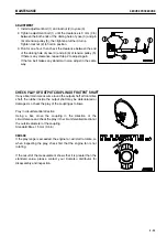
1. Install adjustment bolt (1) and locknut (2) to yoke (3).
2. Tighten adjustment bolt (1) until the clearance is 0 mm (0 in)
between the both ends of the oblong hole of yoke (3) and pin
(6) of tension pulley (5), then tighten a further 3 turns.
Tighten locknut (2) to hold in position.
3. Run for one hour, then check the clearance between the end
of the oblong hole of yoke (3) and pin (6) of tension pulley (5).
If there is any clearance, repeat Step 2 to adjust again.
If the fan belt makes any abnormal noise, adjust in the same
way.
CHECK PLAY OF OUTPUT COUPLING OF OUTPUT SHAFT
If any abnormal noise occurs around the output shaft or front drive
shaft, the rubber inside the output shaft may be deteriorated or
damaged, so check the play of the coupling as follows.
Play in circumferential direction
Using a bar, move the coupling in the direction of the
circumference and check the play in the circumferential direction at
the outside diameter of the coupling.
Standard: Max. 15 mm (0.6 in)
REMARK
If the play range is exceeded, the engine fan will start to rotate, so
when inspecting the play, check first that the engine fan is not
rotating.
If the result of the measurement shows that it is greater than the
standard value, please contact your Komatsu distributor for
disassembly and inspection.
4 - 33
Summary of Contents for HD785-5
Page 2: ... 1 1 ...
Page 4: ... FOREWORD FOREWORD 1 3 ...
Page 5: ... FOREWORD FOREWORD 1 4 ...
Page 15: ... 2 1 ...
Page 19: ... SAFETY SAFETY LABELS POSITION FOR ATTACHING SAFETY LABELS 2 5 ...
Page 47: ... 3 1 ...
Page 132: ... OPERATION OPERATION Brake performance Downhill distace Continuous Tire size 27 00R49 3 86 ...
Page 166: ... 4 1 ...
Page 237: ... 5 1 ...
Page 239: ... SPECIFICATIONS SPECIFICATIONS 5 3 ...
Page 240: ... 6 1 ...
Page 299: ... 7 1 ...


