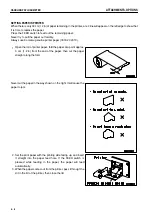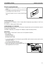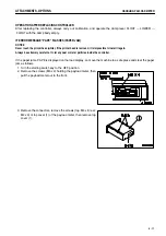
.
ATTACHMENTS, OPTIONS
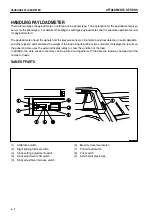
HANDLING PAYLOAD METER
ATTACHMENTS, OPTIONS
HANDLING PAYLOAD METER
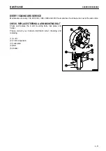
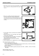
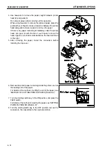
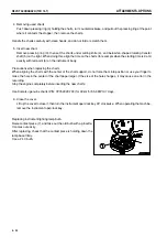
4. Remove the connectors, remove the screws (top: M4 x 8, rear:
M4 x 3) of top cover (1) of the payload meter, then remove top
cover (1).
5. Remove the nut (M4) and the band holding the battery.
Do not wear gloves when carrying out this operation.
Be careful not to let dirt, dust, or metal particles get inside the
controller. Be careful not to drop any nuts or washers inside the
controller.
6. Pull the battery connectors up directly from the printboard to
remove them.
7. Push the connectors of the new battery down straight to
connect them to the printboard.
8. Fit the battery band, then fix the battery to the payload meter
with the nut (M4) and washer (flat spring).
Check that the battery has not moved out of position.
9. Install the top cover.
10. Install the payload meter to its original position on the panel.
After replacing the battery, do as follows.
1) Turn the starting switch to the ON position.
2) Press the memory data clear switch (CLR) twice to delete the data from memory. (The first time, it will flash;
the second time, it will light up and then display the load.)
3) Carry out calibration.
4) After carrying out calibration, operate the dump lever once FLOAT
→
LOWER
→
FLOAT with the dump
body empty.
Replace the battery within 48 hours.
The life of the battery is approx. 2 years.
6 - 10
Summary of Contents for HD785-5
Page 2: ... 1 1 ...
Page 4: ... FOREWORD FOREWORD 1 3 ...
Page 5: ... FOREWORD FOREWORD 1 4 ...
Page 15: ... 2 1 ...
Page 19: ... SAFETY SAFETY LABELS POSITION FOR ATTACHING SAFETY LABELS 2 5 ...
Page 47: ... 3 1 ...
Page 132: ... OPERATION OPERATION Brake performance Downhill distace Continuous Tire size 27 00R49 3 86 ...
Page 166: ... 4 1 ...
Page 237: ... 5 1 ...
Page 239: ... SPECIFICATIONS SPECIFICATIONS 5 3 ...
Page 240: ... 6 1 ...
Page 299: ... 7 1 ...

