background image

OPERATION

OPERATION

OPERATION

CHECK BEFORE STARTING ENGINE

WALK-AROUND CHECK

Before starting the engine, look around the machine and under the machine to check for loose nuts or bolts, or
leakage of oil, fuel, or coolant, and check the condition of the hydraulic system.
Check also for loose wiring, play, and accumulation of dust in places that get very hot and are exposed to extremely
high temperatures.

 WARNING

Be sure to attach the warning sign on the operaation lever of the machine.
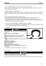
Leakage of oil or fuel, or accumulation of flammable material around high temperature parts, such as the engine muffler or
turbocharger, may cause fire. Check carefully, and if any abnormality is found, repair it or contact your Komatsu distributor.

Always carry out the following items before starting the engine each day.

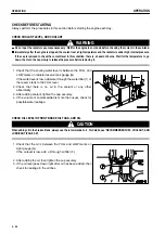
 1. Check the dump body, frame, tires, cylinders, linkage, and hoses for cracks or excessive wear or play.

Check the dump body, frame, tires, cylinders, linkage, and hoses for cracks or excessive wear or play, and carry out
repairs if any problem is found.

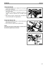
 2. Remove dirt from around engine, battery, radiator, and aftercooler.

Check that there is no dirt or dust accumulated around the engine, radiator or aftercooler. Check also that there is
no flammable material (dry leaves, twigs, etc.) accumulated around the battery, or engine, muffler, turbocharger, or
other high temperature parts of the engine. Remove any dirt or flammable materials that are found.

 3. Check for leakage of water or oil around engine

Check that there is no oil leakage from the engine or coolant leakage from the cooling system. If any problem is
found, repair it.

 4. Check for oil leakage from transmission case, differential case, final drive case, brake oil tank, hydraulic tank,

hose, joint

Check that there is no oil leakage. If any problem is found, repair the place where the oil is leaking.
Check for leakage of oil from the undercover. Check the ground for traces of oil leakage.

 5. Check for loose air cleaner mounting bolts.

Check for the loose bolts. If loose, tighten them.

 6. Check dump body mount rubber

Check for any cracks, embedded foreign objects, or loose bolts.

 7. Check for damage to handrail, loose bolts

Repair any damage and tighten any loose bolts.

3 - 54

Summary of Contents for HD785-5

Page 1: ...essary contact your local distributor for availability NOTICE Unsafe Use of this machine may cause serious injury or Death Operators and maintenance personnel must read this manual before operating or maintaining this machine This manual should be kept near the machine for reference and periodically reviewed by all personnel who will come into contact with it WARNING ...

Page 2: ... 1 1 ...

Page 3: ...sure that you understand them fully Keep this manual in the storage location for the operation and maintenance manual given below and have all personnel read it periodically If this manual has been lost or has become dirty and cannot be read request a replacement manual immediately from Komatsu or your Komatsu distributor If you sell the machine be sure to give this manual to the new owners togeth...

Page 4: ... FOREWORD FOREWORD 1 3 ...

Page 5: ... FOREWORD FOREWORD 1 4 ...

Page 6: ...ation which if not avoided could result in death or serious injury Indicates a potentially hazardous situation which if not avoided may result in minor or moderate injury This word is used also to alert against unsafe practices that may cause property damage Example of safety message using signal word WARNING When standing up from the operator s seat always place the safety lock lever in the LOCK ...

Page 7: ...d inside a triangle and the method of avoiding the hazardous condition is shown inside a circle Komatsu cannot predict every circumstance that might involve a potential hazard in operation and maintenance Therefore the safety messages in this manual and on the machine may not include all possible safety precautions If any proceduresor actions not specifically recommendedor allowed in this manual a...

Page 8: ... USE INTENDED USE DIRECTIONS OF MACHINE In this manual the directions of the machine front rear left right are determined according to the view from the operator s seat in the direction of travel front of the machine 1 7 ...

Page 9: ...he following items PRODUCT IDENTIFICATION NUMBER PIN MACHINE SERIAL NO PLATE It is located on the left front end of the frame The design of the nameplate differs according to the territory ENGINE SERIAL NO PLATE POSITION The engine serial number plate is on the upper right side of viewed from the fan the cylinder block on the intake manifold cover SERVICE METER POSITION It is located on the right ...

Page 10: ...N OF PLATES TABLE TO ENTER SERIAL NO AND DISTRIBUTOR TABLE TO ENTER SERIAL NO AND DISTRIBUTOR Machine serial No Engine serial No Product identification number PIN Distributor name Address Service Personnel Phone Fax 1 9 ...

Page 11: ...NG ENGINE 2 20 BATTERY 2 23 TOWING 2 25 PRECAUTIONS FOR MAINTENANCE 2 26 PRECAUTIONS WITH TIRES 2 32 OPERATION 3 1 GENERAL VIEW 3 2 GENERAL VIEW OF MACHINE 3 2 GENERAL VIEW OF CONTROLS AND GAUGES 3 3 EXPLANATION OF COMPONENTS 3 5 MACHINE MONITOR 3 5 SWITCHES 3 22 CONTROL LEVERS AND PEDALS 3 30 MECHATRONICS EQUIPMENT CONTROLLER 3 34 SAFETY PIN 3 35 DUST INDICATOR 3 35 FUSES 3 36 CAR STEREO 3 38 AIR...

Page 12: ... STORAGE 3 103 PRECAUTIONS BEFORE TRAVELING AFTER LONG TERM STORAGE 3 103 TROUBLESHOOTING 3 104 AFTER RUNNING OUT OF FUEL 3 104 METHOD OF TOWING MACHINE 3 104 IF BATTERY IS DISCHARGED 3 109 OTHER TROUBLE 3 113 MAINTENANCE 4 1 GUIDES TO MAINTENANCE 4 2 OUTLINE OF SERVICE 4 4 HANDLING OIL FUEL COOLANT AND PERFORMING OIL CLINIC 4 4 OUTLINE OF ELECTRIC SYSTEM 4 7 WEAR PARTS 4 8 WEAR PARTS LIST 4 8 REC...

Page 13: ...DAL 6 21 PRECAUTIONS AND METHOD OF USE 6 22 OPERATION OF ABS AND ABS ASR 6 23 EXPLANATION OF COMPONENTS 6 23 OPERATION METHOD 6 25 PRECAUTIONS FOR USE 6 26 TROUBLESHOOTING 6 26 ARSC AUTOMATIC RETARDER SPEED CONTROL 6 27 EXPLANATION OF COMPONENTS 6 28 METHOD OF OPERATION 6 30 TROUBLESHOOTING 6 32 PMC POWERTRAIN MANAGEMENT CONTROLLER AND MOM MESSAGE FOR OPERATION AND MAINTENANCE 6 35 CHECK BEFORE ST...

Page 14: ...UTIONS WHEN HANDLING AUTO GREASING SYSTEM 6 48 POSITION OF EACH INJECTOR 6 52 GREASING POINTS FOR EACH INJECTOR 6 56 HIGH ALTITUDE SPECIFICATIONS 7 1 EXPLANATION OF COMPONENTS 7 2 SERVICE PROCEDURE 7 3 CHECK BEFORE STARTING 7 3 EVERY 2000 HOURS SERVICE 7 4 INDEX 8 1 1 13 ...

Page 15: ... 2 1 ...

Page 16: ...PPLY LOCK WHEN LEAVING OPERATOR S SEAT 2 11 HANDRAILS AND STEPS 2 12 MOUNTING AND DISMOUNTIN 2 12 PREVENTION OF BURNS 2 13 FIRE PREVENTION 2 13 ACTION IF FIRE OCCURS 2 14 WINDOW WASHER LIQUID 2 14 PRECAUTIONS WHEN USING ROPS Roll Over Protective Structure 2 15 PRECAUTIONS FOR ATTACHMENTS 2 15 UNAUTHORIZED MODIFICATION 2 15 SAFETY AT WORKSITE 2 15 WORKING ON LOOSE GROUND 2 16 DO NOT GO CLOSE TO HIG...

Page 17: ...ENTION 2 23 STARTING WITH BOOSTER CABLES 2 24 TOWING 2 25 WHEN TOWING 2 25 PRECAUTIONS FOR MAINTENANCE 2 26 WARNING TAG 2 26 KEEP WORK PLACE CLEAN AND TIDY 2 26 APPOINT LEADER WHEN WORKING WITH OTHERS 2 26 STOP ENGINE BEFORE CARRYING OUT INSPECTION AND MAINTENANCE 2 27 TWO WORKERS FOR MAINTENANCE WHEN ENGINE IS RUNNING 2 28 PROPER TOOLS 2 28 HANDLING SUSPENTION CYLINDER 2 29 PERSONNEL 2 29 WORK UN...

Page 18: ...e correct place and always keep them clean When cleaning them do not use organic solvents or gasoline These may cause the labels to peel off There are also other labels in addition to the warning signs and safety labels Handle those labels in the same way If the labels are damaged lost or cannot be read properly replace them with new ones For details of the part numbers for the labels see this man...

Page 19: ... SAFETY SAFETY LABELS POSITION FOR ATTACHING SAFETY LABELS 2 5 ...

Page 20: ...FETY LABELS SAFETY LABELS 1 Roll over protective structure ROPS 09620 30202 2 Caution for checking engine room 09667 A0880 3 Caution for opening hydraulic tank cap Caution for opening radiator cap 09653 A0641 2 6 ...

Page 21: ...der 09659 A0881 5 Warnings for electric wire Warnings for crush hazard when inspection and maintenance Warnings for inspection of emergency steering system emergency brake system Warning for leaving operator s seat stopping engine Warning for retarder oil temperature 569 93 61730 2 7 ...

Page 22: ...ELS 6 Cautions before starting Cautions when traveling in reverse Cautions for operating hoist control lever dump lever 569 93 61720 7 Caution when handling battery cable 09808 A1681 8 Exhaust pipe is hot 09817 A1103 2 8 ...

Page 23: ...AFETY LABELS 9 Caution for avoiding falling down 09805 C0881 10 Caution when handling battery This plate is stick on the machine by the battery maker 11 Jump start prohibited 09842 A0481 This plate is stick on the starting motor 2 9 ...

Page 24: ...ey may catch on control levers or other protruding parts If you have long hair and it hangs out from your hard hat there is a hazard that it may get caught up in the machine so tie your hair up and be careful not to let it get caught Always wear a hard hat and safety shoes If the nature of the work requires it wear safety glasses mask gloves ear plugs and safety belt when operating or maintaining ...

Page 25: ...Do not stick suction pads to the window glass Suction pads act as a lens and may cause fire Do not use cellular telephones inside the operator s compartment when driving or operating the machine Never bring any dangerous objects such as flammable or explosive items into the operator s compartment ALWAYS APPLY LOCK WHEN LEAVING OPERATOR S SEAT Before adjusting or standing up from the operator s sea...

Page 26: ...both hands and one foot with the handrails and steps to ensure that you support yourself Do not grip the dump lever when getting on or off the machine Never climb on the engine hood or covers where there are no non slip pads Before getting on or off the machine check the handrails and steps and if there is any oil grease or mud on them wipe it off immediately In addition repair any damage and tigh...

Page 27: ...reeze and window washer liquid are particularly flammable and can be hazardous To prevent fire always observe the following Do not smoke or use any flame near fuel or oil Stop the engine before refueling Do not leave the machine while adding fuel or oil Tighten all fuel and oil caps securely Do not spill fuel on overheated surfaces or on parts of the electrical system Use well ventilated areas for...

Page 28: ...hey are loose they may vibrate during operation and rub against other parts This may lead to damage to the hoses and cause high pressure oil to spurt out leading to fire damage or serious injury Explosion caused by lighting equipment When checking fuel oil battery electrolyte window washer fluid or coolant always use lighting with anti explosion specifications If such lighting equipment is not use...

Page 29: ...y injuries accidents or product failures resulting from the use of unauthorized attachments or parts will not be the responsibility of Komatsu When installing and using optional attachments read the instruction manual for the attachment and the general information related to attachments in this manual UNAUTHORIZED MODIFICATION Any modification made without authorization from Komatsu can create haz...

Page 30: ... 17 ft 187 000 V Over 6 m 20 ft 275 000 V Over 7 m 23 ft 500 000 V Over 11 m 36 ft Even going close to high voltage cables can cause electric shock which may cause serious burns or even death Always maintain a safe distance see the table on the right between the machine and the electric cable Check with the local power company about safe operating procedure before starting operations To prepare fo...

Page 31: ...tand the meaning of all signals and signs before starting work ASBESTOS DUST HAZARD PREVENTION Asbestos dust in the air can cause lung cancer if it is inhaled There is danger of inhaling asbestos when working on jobsites handling demolition work or work handling industrial waste Always observe the following Spray water to keep down the dust when cleaning Do not use compressed air for cleaning If t...

Page 32: ...t the pedals work properly Adjust the operator s seat to a position where it is easy to carry out operations and check that there is no damage or wear to the seat belt or mounting clamps Check the operation of the instruments and gauges check the angle of the mirror and check that the control levers are all at the Neutral position Before starting the engine make sure that the safety lock lever is ...

Page 33: ...the battery or start the engine with a different power source There is a hazard that this will ignite the battery and cause the battery to explode Before charging or starting the engine with a different power source melt the battery electrolyte and check that there is no leakage of electrolyte before starting Drain water in the air tank If there is no sound of the air being released when the servi...

Page 34: ...blem is found carry out repairs immediately PRECAUTIONS WHEN TRAVELING FORWARD OR REVERSE Before travelling check again that there is no one in the surrounding area and that there are no obstacles Before travelling sound the horn to warn people in the area Always operate the machine only when seated Always fasten your seat belt If another person is allowed on the machine that person may sit only i...

Page 35: ...there is a hazard that the machine may slip If the engine should stop on a slope apply the brakes fully and apply the parking brake also to stop the machine Do not shift the gear while traveling downhill or travel downhill with the transmission in neutral If this is neglected the engine does not work as a brake and that is dangerous Be sure to set the transmission in one of the lower gear speeds I...

Page 36: ... Reduce the speed and use the engine as a brake while applying the foot brake intermittently depress the brake intermittently several times If necessary lower the bucket to the ground to stop the machine When the loaded materials in the dump body are frozen do not dump There is a danger that the machine could tip over PRECAUTIONS FOR PARKING Park the machine on firm level ground Select a place whe...

Page 37: ... with large amount of water If acid gets into your eyes flush them immediately with large amount of water and seek medical attention Before working with batteries turn the starting switch to the OFF position As there is a hazard that sparks will be generated always do as follows Do not let tools or other metal objects make any contact between the battery terminals Do not leave tools or other metal...

Page 38: ... machine There is a hazard that the machine will move when the power is connected Be sure to connect the positive cable first when installing the booster cables Disconnect the negative cable ground side first when removing them When removing the booster cables be careful not to let the booster cable clips touch each other or to let the clips touch the machine Always wear safety glasses and rubber ...

Page 39: ... OF TOWING MACHINE PAGE 3 104 Always confirm that the wire rope or drawbar used for towing has ample strength for the weight of the machine being towed Never use a wire rope which has cut strands A reduced diameter B or kinks C There is danger that the rope may break during the towing operation Always wear leather gloves when handling wire rope Never tow a machine on a slope During the towing oper...

Page 40: ... serviceman is carrying out service or maintenance of the machine it may lead to serious injury KEEP WORK PLACE CLEAN AND TIDY Do not leave hammers or other tools lying around in the work place Wipe up all grease oil or other substances that will cause you to slip Always keep the work place clean and tidy to enable you to carry out operations safely If the work place is not kept claen and tidy the...

Page 41: ...he machine on firm level ground Select a place where there is no hazard of falling rocks or landslides or of flooding if the land is low Lower the dump body and stop the engine Set parking brake valve lever to the PARKING position and put blocks 1 under the tires to prevent the machine from moving 2 27 ...

Page 42: ...m moving Also set parking brake valve lever to the PARKING position to prevent the machine from moving When carrying out operations near the fan fan belt or other rotating parts there is a hazard of being caught in the parts so be careful not to come close Do not touch any control levers If any control lever must be operated give a signal to the other workers to warn them to move to a safe place N...

Page 43: ...the safety pin securely When you use safety pin see SAFETY PIN PAGE 3 35 NOISE When carrying out maintenance of the engine and you are exposed to noise for long periods of time wear ear covers or ear plugs while working If the noise from the machine is too loud it may cause temporary or permanent hearing problems PRECAUTIONS WHEN USING HAMMER When using a hammer pins may fly out or metal particles...

Page 44: ...y a jet of high pressureoil and suffer injury to your skin or eyes wash the place with clean water and consult a doctor immediately for medical attention HANDLING HIGH PRESSURE HOSES PIPING If oil or fuel leaks from high pressure hoses it may cause fire or defective operation which may lead to serious injury If any loose bolts are found stop work and tighten to the specified torque If any damaged ...

Page 45: ...safety components with a strong relationship to safety such as hoses and seat belts must be replaced at periodic intervals Replacement of safety critical parts See PERIODIC REPLACEMENT OF SAFETY CRITICAL PARTS PAGE 4 13 The material of these components naturally changes over time and repeated use causes deterioration wear and fatigue As a result there is a hazard that these components may fail and...

Page 46: ...do not fit the tire there is a problem with the tire or rim parts Always contact your Komatsu distributor for repairs If the rim parts are not fitted properly when the tire is being pumped up there is danger that the rim parts may fly off so set up a protective fence around the tire and do not stand directly in front of the rim Stand beside the tread when pumping up the tire Do not adjust the tire...

Page 47: ... 3 1 ...

Page 48: ... OPERATION GENERAL VIEW GENERAL VIEW GENERAL VIEW OF MACHINE 1 2 3 Dump body Rear wheel Front wheel 4 5 Turn signal light Head lamp 3 2 ...

Page 49: ...achine monitor Retarder control lever Cigarette lighter Shift lever Parking brake valve lever 10 11 12 13 14 15 16 17 18 Shift limiter switch Power mode selector switch if equipped Emergency brake lever Emergency steering switch Message display for PMC if equipped Engine emergency stop switch Accelerator pedal Brake pedal Differential lock pedal if equipped 3 3 ...

Page 50: ... Enlargement of machine monitor 1 2 3 4 Caution pilot lamp bulb check switch Starting switch Preheating switch AISS LOW switch 5 6 7 8 Panel dimmer switch Hazard lamp switch Front brake cut off switch Exhaust brake switch 3 4 ...

Page 51: ...ere is probably a failure or disconnection in that circuit therefore contact your Komatsu distributor to have the circuit checked When the starting switch is at the ON position if the shift lever is not at the neutral position then the transmission shift lever position pilot lamp 1 and the central warning lamp will flash and the alarm buzzer will continue to sound intermittently At this time when ...

Page 52: ... to 07 is displayed in turn at the upper right of the liquid crystal display on the monitor panel stop the machine once Then take the corrective action as follows after checking user code 1 User code 02 Park the machine at a safe location and contact your Komatsu distributor 04 Carry out an emergency stop Stop the engine and contact your Komatsu distributor 01 Carry out checks and maintenance acco...

Page 53: ... If there is any abnormallity for the caution items the monitor for the corresponding abnormal area lights up 1 2 3 4 Battery charge Emergency steering Parking brake Dump body actuation caution 5 6 7 Transmission filter clogging Fuel level Maintenance caution lamp if equipped BATTERY CHARGE This 1 notifies the operator of any abnormality in the charging system when the engine is running If it ligh...

Page 54: ...e is applied It goes on and out respectively responding to the parking brake lever shifting of PARK TRAVEL DUMP BODY ACTUATION CAUTION This monitor 4 lights up when the dump body control lever is at any position other than FLOAT or when the body is lifted Always set the lever to the FLOAT position and lower the body during traveling TRANSMISSION FILTER CLOGGING This monitor 5 notifies the operator...

Page 55: ...ays user code 01 at the same time carry out check replenishment or replacement Insufficient oil in the front brake oil tank Insufficient oil in the transmission case Insufficient oil in the hydraulic oil tank Clogging of the transmission filter on the tank side Clogging of the full flow filter the engine oil filter Clogging of the hydraulic oil filter Wear of the rear brake disc right hand Wear of...

Page 56: ...section lights up or flashes and the central warning light flashes 1 2 3 4 5 Air pressure Engine water temperature Torque converter oil temperature Retarder oil temperature Radiator water level 6 7 8 9 Engine oil pressure Angle warning Rear brake caution lamp Steering oil temperature AIR PRESSURE This monitor 1 warns the operator that the air pressure inside the air tank has dropped If it flashes ...

Page 57: ...sen If it flashes and displays user code 05 at the same time stop the machine and run the engine under no load at a mid range speed until the torque converter oil temperature gauges enters the green range RETARDER OIL TEMPERATURE This monitor 4 warns the operator that the retarder oil temperature has risen If it flashes and displays user code 05 at the same time stop the machine place the shift le...

Page 58: ... and displays action code 07 at the same time lower the body and move the machine to a safe stable place REAR BRAKE CAUTION LAMP This monitor 8 lights up if the brake oil pressure drops under the normal value If it lights up and display user code 04 at the same time immediately check the rear brake system After checking and repairing depress the rod for the overstroke sensor on the brake chamber I...

Page 59: ...ot Rear brake pilot retarder Differential lock pilot if equipped Lockup pilot lamp Shift limiter pilot lamp 7 8 9 10 11 12 High beam Turn signal pilot lamp Shift indicator with lockup display Transmission shift lever position pilot lamp Auto suspension mode display lamp Power mode display lamp if equipped PREHEATING MONITOR This lamp lights up when the electrical heater for preheating the engine i...

Page 60: ...rake is depressed or the retarder control lever is pulled and the rear brake is applied DIFFERENTIAL LOCK PILOT If equipped This pilot lamp 4 lights up when the differential lock pedal if equipped is depressed and the differential lock is actuated LOCKUP PILOT LAMP This pilot lamp 5 lights up when the torque converter lockup is engaged and the transmission is shifted to direct drive 3 14 ...

Page 61: ...mps are set to high beam TURN SIGNAL PILOT LAMP This pilot lamp 8 flashes at the same time as the turn signal lamp flashes SHIFT INDICATOR This monitor 9 displays the transmission shift range speed range When the key was turned ON if the shift lever is operated it will display 2 at the lever position D 1 at the 5 L position and R at the R position even if the engine is stopped 3 15 ...

Page 62: ... according to the size of the load use of the brake operation of the steering and operation of the dump control Normally it is set to the soft mode when the dump truck is traveling empty and to the medium mode when it is traveling loaded When the foot brake is operated or the machine is suddenly turned or the dump control is operated the suspension mode is switched to insure the stability of the m...

Page 63: ...dometer Engine tachometer Service meter Odometer Fuel gauge 6 7 8 9 Air pressure gauge Engine water temperature gauge Torque converter oil temperature gauge Retarder oil temperature gauge SPEEDOMETER This meter 1 indicates the travel speed of the machine 3 17 ...

Page 64: ... of operation of the machine If the engine is running the service meter will advance even if the machine is not moving The meter advances by 1 for every one hour of operation regardless of the engine speed ODOMETER This 4 indicates the distance traveled in kilometers FUEL GAUGE This gauge 5 indicates the amount of fuel in the fuel tank The green range should be lighted up during operation If only ...

Page 65: ...o load at a mid range speed and wait until the green range lights up If the red range lights up the engine output of the machine equipped with an electronic governor is automatically limited TORQUE CONVERTER OIL TEMPERATURE GAUGE This gauge 8 indicates the torque converter oil temperature The green range should be lit up during operation If the red range lights up during operation the alarm buzzer...

Page 66: ...alarm buzzer sounds intermittently Stop the machine then take appropriate corrective action according to the user code 1 2 Engine Mechatronics related Automatic transmission Mechatronics related 3 Mechatronics related parts Excluding 1 and 2 above ENGINE Mechatronics related If an abnormality is detected in the mechatronics related parts of the engine control system this lamp 1 flashes to warn of ...

Page 67: ...ARNING LAMP If the machine is in the following condition this lamp will flash When an abnormality has occurred in any of B caution items When the abnormalities has occurred refered to CAUTION ITEMS PAGE 3 7 If the machine is in the following condition this lamp will flash and at the same time the alarm buzzer will sound intermittently When an abnormality has occurred in any of EMERGENCY STOP ITEM ...

Page 68: ...t brake switch Front brake cut off switch Hazard lamp switch Night lighting dimmer switch AISS LOW switch Preheating switch 10 11 12 13 14 15 16 17 18 19 Power mode selector switch Emergency steering switch Emergency brake lever Shift limiter switch Parking brake valve lever Engine emergency stop switch Cigarette lighter Horn button Wiper switch Room lamp switch 3 22 ...

Page 69: ...n START position This is the position to start the engine Hold the key at this position while cranking Release the key immediately after the engine has been started The key will return to the ON position when released LAMP SWITCH This 2 lights up the head lamps side clearance lamps tail lamps machine monitor lighting and rear lamps a position OFF b position Side clearance lamps tail lamps rear lam...

Page 70: ...T BRAKE SWITCH This switch 4 shows the operating condition of the exhaust brake If it is pushed once it lights up and it goes off when it is pushed again OFF position Light is off The exhaust brake is actuated when the brake pedal is depressed or the retarder control lever is operated if the torque converter is in the lockup condition ON position Light is on The exhaust brake is actuated when the ...

Page 71: ...pedal is depressed the brakes are applied to both the front and rear wheels ON position Light is on When the brake pedal is depressed the front brakes are not applied The brakes are applied only to the rear wheels When traveling at high speed on a road surface that has been properly watered set the front brake cut off switch to OFF position lamp off and normally use the retarder control lever to c...

Page 72: ...ake or retarder brake at ON position idling is set at low speed When starting by setting the parking brake at OFF position idling is set at high speed 2 Detecting the water temperature idle is set at high speed automatically under the low temperature condition and the warm up time is shortened PREHEATING SWITCH This switch 9 operate an electric heater to heat the intake air for the engine If it is...

Page 73: ...eering is actuated it is possible to use the dump lever to raise the dump body Automatic emergency steering will be actuated automatically in the following cases When hydraulic pump for steering has trouble When engine has stopped during operation When the automatic emergency steering is actuated stop the machine promptly and perform inspection If the key switch is turned ON when the machine is st...

Page 74: ...NG Parking brake actuated TRAVEL Parking brake is released When the lever is set to the PARKING position the parking brake pilot lamp lights up When the lever is set to the PARKING position if the gear shift lever is at any position other than N the central warning lamp will flash and the alarm buzzer will sound If the air pressure drops and goes below 0 22MPa 2 2kgf cm2 31 24PSI the emergency bra...

Page 75: ...our cigarette HORN BUTTON When the horn button 17 in the center of the steering wheel is pressed the horn will sound WIPER SWITCH This switch 18 is used to operate the wiper INT position Wiper moves intermittently OFF LOW position Wiper moves at low speed HI position Wiper moves at high speed When the switch is pressed washer fluid is sprayed out ROOM LAMP SWITCH This 19 is used to switch the room...

Page 76: ...NENTS CONTROL LEVERS AND PEDALS 1 2 3 4 Brake pedal Accelerator pedal Shift lever Safety lock 5 6 7 Dump lever Retarder control lever Differential lock pedal if equipped BRAKE PEDAL This pedal 1 is used to apply the wheel brakes 3 30 ...

Page 77: ...rse if the dump lever is not at the FLOAT position Set the dump lever to the FLOAT position before moving the shift lever to the R position 5 L position These positions are used in places where it is difficult to travel at high speed or when traveling on soft ground or when starting the machine off on a slope when it is loaded They are also used when going downhill if it is needed to use the braki...

Page 78: ... is not at the FLOAT position and when the dump body has risen if the shift lever is not at the N neutral position the central warning lamp will flash and the alarm buzzer will sound The shift lever must not be returned to the N neutral position while traveling Release the accelerator pedal and run the engine at low idle when moving the shift lever from the N neutral position to the forward or rev...

Page 79: ...r must not be used as a parking brake This lever 6 is used to operate the retarder which applies the rear wheel brake when going downhill The more the lever is pulled the greater the braking force becomes When the retarder is actuated the rear brake pilot lamp lights up For details see TRAVELING DOWNHILL PAGE 3 81 When leaving the operator s seat always apply the parking brake DIFFERENTIAL LOCK PE...

Page 80: ...ON CONTROLLER PAGE 3 119 ENGINE CONTROLLER For this controller 2 the last two digit number of the service code is displayed in the inspection window to identify the location of the abnormality When the condition is normal 0 0 is displayed For the method to check the service code when the abnormality occurs see SERVICE CODE PAGE 3 118 SUSPENSION CONTROLLER For this controller 3 the last two digit n...

Page 81: ...e with the dump body raised Raise the dump body fully insert safety pins 1 Always insert the safety pins on both sides STOWING SAFETY PIN Safety pins 1 are stowed in the towing bracket of the rear axle housing DUST INDICATOR This device indicates clogging of the air cleaner element When red piston 1 appears in the transparent part of this indicator the element is clogged Immediately clean the elem...

Page 82: ... holder replace the fuse FUSE CAPACITY AND CIRCUIT NAME Fuse box I No Fuse capacity Circuit name 1 10A Car radio car stereo 2 10A Horn switch 3 10A Cigarette lighter 4 20A Turn signal indicator lamp fog lamp if equipped 5 10A Engine start relay neutral relay 6 20A Head lamp low beam stop lamp room lamp 7 20A Head lamp high beam side clearance lamp tail lamp night lighting 8 10A Backup lamp backup ...

Page 83: ...oad relay if equipped 15 20A Payload external display lamp if equipped 16 5A PMC if equipped 17 10A Start switch radio back up emergency engine stop solenoid if equipped electronic governor engine stop motor 18 10A T M controller engine controller if equipped PMC if equipped 19 10A Emergency steering 20 10A Direct from battery spare Fuse box III No Fuse capacity Circuit name 21 10A AISS motor 22 2...

Page 84: ...Loudness button Time Radio display selector button Tape eject button 8 9 10 11 12 13 14 Cassette door Fast forward rewind buttons Preset buttons Metal tape button Manual tuning buttons Seek tuning buttons Band selector button A B C D Band display Metal tape display FM stereo reception display Loudness display E F G Tape direction display Preset channel display Time Frequency display 3 38 ...

Page 85: ...y is memorized in the auto store REMARK The auto store function cannot be used when the channel display is flashing When the display is flashing the preset scan function is being used Preset scan If this button is pressed for less than 0 5 second while in radio reception programs from the six preset stations in the same band will be broadcast one after another for 5 seconds each starting from No 1...

Page 86: ...easily by emphasizing the low tone when the low tones are weak Push button Actuated ON Push button again Canceled OFF TIME RADIO DISPLAY SELECTOR BUTTON This button 6 is used to switch between the Radio tape display and the Time display Correcting the time Press the button to set the time display A Correcting hour Keep the DISP button pressed and press the bottom H of the TUNING button to correct ...

Page 87: ... press the button pointing in the same direction as the lighted arrow indicating the direction of play the tape will be fast forwarded if you press the button pointing in the opposite direction the tape will rewind To stop the tape lightly press the button that is not locked The fast forward or rewind operation will be canceled If the fast forward and rewind buttons are pressed at the same time th...

Page 88: ... for FM when TUN button is pressed the frequency goes down 9 kHz for AM or 0 1 MHz for FM If the button is pressed down and held the frequency will change continuously SEEK TUNING BUTTONS These buttons 13 are used to seek tuning When the SEEK UP button is pressed the search automatically goes up when the SEEK DOWN button is pressed the search automatically goes down When the next station that can ...

Page 89: ...ton 1 to select MW AM FM1 or FM2 then use the manual tuning button to select the frequency of the broadcasting station 3 Press manual memory button 2 or seek tuning button 3 4 Press preset button 4 of the number to be preset for 2 seconds while the frequency display is being shown on the display The preset channel and frequency are displayed and the presetting is completed 5 Repeat Steps 2 to 4 to...

Page 90: ...IO 1 Turn the starting switch ON then turn power switch 1 ON 2 Set band selector button 2 to AM or FM 3 Select the station with the preset buttons or manual tuning button 3 4 Adjust the volume balance and tone as desired 5 When turning the radio OFF turn power switch 1 to the left until it clicks REMARK To switch to the radio when listening to a cassette press the cassette eject button to stop the...

Page 91: ...ay is pointing to the right the top side is being played if the arrow is pointing to the left the bottom side is being played When the tape reaches the end it is automatically reversed and the other side starts to play 3 When finished with the tape press the cassette eject button to eject the tape and automatically switch to the radio REVERSING TAPE When listening to the tape press both FAST FORWA...

Page 92: ... in alcohol if the equipment is extremely dirty NOTICE Handling cassette tape Clean the tape head approx once a month with a commercially available head cleaning tape Do not leave the tape any place where it is exposed to direct sunlight any place that is excessively dusty or any place where there is a magnetic field Do not use 120 minute tapes The tape is thin and it easily gets caught up inside ...

Page 93: ...t even on dusty jobsites GENERAL LOCATIONS ON CONTROL PANEL 1 2 3 Fan switch Air conditioner switch Mode selector switch 4 5 RECIRC FRESH selector switch Temperature control switch FAN SWITCH This switch 1 can be used to adjust the air flow to 4 stages This switch also acts as the main switch for the air conditioner When the switch is pressed the indicator lamp above the switch lights up to indica...

Page 94: ...five vent modes are available FACE FACE FOOT FOOT FOOT DEF DEF When the switch is pressed the indicator lamp above the switch lights up to display the vent mode RECIRC FRESH SELECTOR SWITCH This switch 4 changes between recirculation of the internal air RECIRC or intake of external air FRESH When pressing the switch the indicator lamp on the top of switch lights up RECIRC This switch 4 is used whe...

Page 95: ...switch to set the temperature The settings for each mode are retained in memory even when the starting switch is turned OFF However in the following cases the settings must be made again When the machine has been out of use for more than 7 days When the battery voltage is extremely low When there has been abnormal interference from outside When the fan switch is turned OFF the setting is not kept ...

Page 96: ... THE AIR CONDITIONER REGURARLY To lubricate each part of the compressor operate cooling dehumidifying and heating for 3 to 5 minutes once a month at low idle Also check the amount of cooling gas twice a year REMARK If the temperature inside the cab is low the air conditioner may not work In such cases use the recirculated air to warm up the inside of the cab then turn the air conditioner switch on...

Page 97: ...e at low speed and set the temperature control lever to the central position Clean the air filter and check the refrigerant For details see CLEAN AIR CONDITIONER AIR FILTER PAGE 4 24 and CHECK REFRIGERANT GAS LEVEL PAGE 4 25 To enable the air conditioner to perform to the full and to maintain a pleasant working environment always contact your Komatsu distributor to have the air conditioner refille...

Page 98: ...LOCATIONS ON CONTROL PANEL 1 Heater switch 2 Vent selector knob HEATER SWITCH This switch is used for turning the heater ON OFF and for adjusting the air flow Stopped OFF 1 Low 2 High VENT SELECTOR KNOB This is used to select the vent 1 Foot 2 Defroster 3 52 ...

Page 99: ...nt from the radiator after at the end of each day Be sure to change the water hose every two years DAILY INSPECTION If malfunctions are found as follows go to the car dealer for repair Scratch cracks or swelling of hose Water leaks from the joint of water hose Removal of protection cover for the water hose Broken heater unit bracket or loosening of heater unit installation bolts Since this heater ...

Page 100: ... carry out repairs if any problem is found 2 Remove dirt from around engine battery radiator and aftercooler Check that there is no dirt or dust accumulated around the engine radiator or aftercooler Check also that there is no flammable material dry leaves twigs etc accumulated around the battery or engine muffler turbocharger or other high temperature parts of the engine Remove any dirt or flamma...

Page 101: ... belt can be seen or if the clamps are broken or deformed replace the seat belt 11 Check cracks and damage of ROPS if equipped and check for loose bolts Check if any bolt is loose or damaged If it is loos tighten up torque 1720 196 N m 175 20kgf m 1265 8 144 7 lbft If it is loose replace it with Komatsu genuine bolt 12 Inspect tires WARNING If worn or damaged tires are used they may burst and caus...

Page 102: ...evel is between the FULL and LOW marks on radiator reserve tank gauge G If the water level is low add water through the water filler 1 of the reserve tank to the FULL level 2 Check that there is no oil in the coolant or any other abnormality 3 After adding coolant tighten the cap securely 4 If the volume of coolant added is more than usual check for possible water leakage CHECK OIL LEVEL IN FRONT ...

Page 103: ...e CHECK CLEAN OR REPLACE AIR CLEANER PAGE 4 19 3 After checking cleaning or replacing press dust indicator 1 to return the red piston to its original position DRAIN WATER FROM AIR TANK 1 After starting the engine pull ring 1 of the tank drain valve to drain the water from the tank 2 Carry out the same operation after completing work NOTICE In cold areas there is danger of the water freezing so dra...

Page 104: ...n plug 1 and loosen drain valve 2 to drain the excess engine oil then check the engine oil level again 6 If the oil level is correct tighten the handle of the oil filler cap securely REMARK When checking the oil level after the engine has been operated wait for at least 15 minutes after stopping the engine The dipstick has the oil level marked on both sides ENGINE STOPPED for measuring when the en...

Page 105: ...evel changes according to the oil temperature so carry out the check after completing the warming up operation Check that the torque converter oil temperature gauge is in green range A on the monitor panel During operations or when the engine is running at idling after operations the oil level be above G2 When checking the oil level with the engine stopped check with sight gauge G1 as a guide line...

Page 106: ...w of sight gauge G add oil through oil filler F CHECK OIL LEVEL IN REAR BRAKE COOLING OIL TANK ADD OIL WARNING When removing the oil filler cap oil may spurt out so turn the cap slowly to release the internal pressure before removing the cap 1 Check with sight gauge G 2 If the oil level is not up to the window of sight gauge G add oil through oil filler F DRAIN WATER SEDIMENT FROM FUEL TANK Loosen...

Page 107: ... becomes clogged the pressure inside the tank will go down and the fuel may not flow so clean the breather hole from time to time CHECK WHEEL HUB NUTS TIGHTEN Check for loose hub nuts and if any are loose tighten 3 or 4 times to the specified torque in the order given in the diagram Tightening torque 2210 245 N m 225 25 kgf m 1627 4 180 8 lbft When thread are not coated with grease 1720 196 N m 17...

Page 108: ...Before starting the engine turn the starting switch to the ON position 2 Check that all monitor lamps gauges and the central warning lamp light up for approx 3 seconds and that the alarm buzzer sounds for approx 1 second REMARK When this is done the speedometer should display 88 When the starting switch is turned to the ON position the pilot lamp at the transmission shift lever position will flash...

Page 109: ...e engine speed and set the shift lever to N position Set parking brake valve lever to PARKING position CHECK EMERGENCY STEERING Check manual emergency steering 1 Turn the starting switch key to the ON position 2 Turn emergency steering switch 1 ON and check that the steering wheel can be operated If the steering wheel cannot be operated please contact your Komatsu distributor Check auto emergency ...

Page 110: ...re is any accumulation of flammable material around the battery and remove such flammable material Please contact your Komatsu distributor for investigation and correction of any problems found CHECK INFLATION PRESSURE OF TIRES Measure the inflation pressure with a tire pressure gauge while the tires are cool before starting work Check for damage or wear to the tires and the rims Check for loose w...

Page 111: ...n release the lever Adjustment range Seat surface approx 2 7 up and down C Setting seat for operator s weight Turn grip 3 under the seat to adjust weight adjustment scale 4 to your own weight Adjustment range 50 to 120kg 110 to 265 lb REMARK To make the seat softer adjust the weight to make it lighter to make the seat harder adjust the weight to make it heavier When traveling on rough road surface...

Page 112: ...alf of the belt twisted Fastening and removing belt 1 Sit on the seat depress the brake pedal fully and adjust the seat so that your back is pressed against the backrest 2 Sit on the seat take buckle 1 and tongue 3 in your left and right hands insert tongue 3 into buckle 1 and pull the belt to check that it is securely locked 3 When removing the belt press button 2 of buckle 1 to release the belt ...

Page 113: ...TILT WARNING Always stop the machine before adjusting the tilt of the steering wheel The tilt of the steering wheel can be adjusted to the front and rear and up and down Pull lever up and set the steering wheel to the desired position then push lever down to lock the steering wheel securely in position Adjustment range Front rear 5 degrees Up 30 mm 1 2 in Down 20 mm 0 8 in 3 67 ...

Page 114: ...tion 1 Check that parking brake valve lever 1 is at the PARKING position 2 Check that gear shift lever 2 is at the N position REMARK If the gear shift lever is not at the N neutral position the engine will not start If the starting switch is turned to the ON position when the gear shift lever is not at N neutral the transmission shift lever position pilot lamp and the central warning lamp will fla...

Page 115: ... OPERATION OPERATION OPERATION OPERATION 5 Check that there is no abnormality on the machine monitor or maintenance monitor when the key in starting switch 5 is turned to the ON position 3 69 ...

Page 116: ...sound the horn and start the engine Exhaust gas is toxic When starting the engine in confined spaces be particularly careful to ensure good ventilation NOTICE Do not keep the starting motor rotating continuously for more than 20 seconds If the engine will not start wait for at least 2 minutes before trying to start the engine again 1 Turn the key of starting switch 1 to the START position to start...

Page 117: ...or rotating continuously for more than 20 seconds If the engine will not start wait for at least 2 minutes before trying to start the engine again 1 Turn the key of starting switch 1 to the ON position 2 The preheating will start automatically and the preheating pilot lamp will light up The pre heating times are as shown below Ambient temperature Preheating time 0 C to 5 C 5 C to 10 C 30 to 40 sec...

Page 118: ... OPERATION OPERATION OPERATION OPERATION 4 When the engine starts release the key in starting switch 1 The key will return automatically to the ON position 3 72 ...

Page 119: ... Do not run the engine at low idle or high idle continuously for more than 20 minutes If it is necessary to continue to run the engine at idle apply a load from time to time or run the engine at a mid range speed After starting the engine do not immediately start operations First perform the following operations and checks 1 After starting the engine run the engine at idle for 5 minutes for warmin...

Page 120: ...the engine at low idle for about 5 minutes to cool down gradually 2 Turn the key of starting switch 1 to the OFF position to stop the engine 3 Remove the key from starting switch 1 CHECKS AFTER STOPPING ENGINE 1 Walk around the machine and check the body work and undercarriage and check also for leakage of oil and water 2 Fill the fuel tank 3 Check the engine compartment for paper and debris Clean...

Page 121: ...s travel path of any obstacle Pay a particular attention to the blind spot at the rear of the machine when traveling the machine in reverse 1 Check that there is no warning display on the machine monitor 2 Check that your seat belt is fastened and that dump lever 1 is at the FLOAT position 3 Depress the brake pedal fully Check that air pressure gauge 2 is in the green range then set parking brake ...

Page 122: ...elerator pedal before shifting from N to R or F 5 Depress accelerator pedal 6 to move the machine off NOTICE If the parking brake is not released and the shift lever is shifted to a position other than N the central warning lamp will flash and the alarm buzzer will sound If the dump lever is not at the FLOAT position and the shift lever is shifted to a position other than N the central warning lam...

Page 123: ...dal 2 to move the machine off NOTICE The machine cannot travel in reverse if the dump lever is not at the FLOAT position Place the dump lever at the FLOAT position before operating to the R position When shifting between FORWARD and REVERSE stop the machine completely and run the engine at low idle when shifting the lever After moving the gear shift lever do not depress the accelerator until you d...

Page 124: ...s or when parking the machine after stopping it NORMAL STOPPING Release accelerator pedal 1 and depress brake pedal 2 to stop the machine STOPPING IN EMERGENCY If there should be a failure in the foot brake stop the machine as follows WARNING When the machine stops put blocks under the tires immediately Immediately after making an emergency stop the parking brake disc will be at high temperature s...

Page 125: ...g brake valve lever 3 to the right to the PARKING position 4 If an emergency stop has been made put blocks under the tires immediately then try to find the cause and repair it on site 5 After the emergency operation of parking brake and emergency brake see RELEASE METHOD WHEN PARKING BRAKE AND EMERGENCY BRAKE HAVE BEEN ACTUATED IN EMERGENCY PAGE 3 107 in case that it is necessary to release the br...

Page 126: ...il you detect that the transmission clutch has engaged Do not operate the gear shift lever with the accelerator pedal depressed This will cause a big shock and will also reduce the service life of the machine SHIFTING UP 1 When accelerator pedal 2 is depressed to accelerate the machine the lockup clutch is engaged to shift the transmission to direct drive 2 If the machine is accelerated further th...

Page 127: ... monitor to go out If the retarder loses its effect when it is used for traveling downhill do as follows 1 Release the retarder brake completely then operate the retarder lever again 2 If the retarder still has no effect even when the retarder lever is operated again return the retarder lever completely to the released position then depress the brake pedal to stop the machine and contact your Koma...

Page 128: ...retarder lever 2 run the engine at a speed of at least 1 800 rpm and travel so that the retarder brake oil temperature gauge is in the green range For machines equipped with an exhaust brake using the exhaust brake can provide more secure braking force for increased safety and will also improve the durability of the brake For details of handling the exhaust brake see EXHAUST BRAKE SWITCH PAGE 3 24...

Page 129: ... draw a horizontal line 4 Take the point where it crosses the performance curve as C and draw a perpendicular line down Take the point where this line crosses the travel speed scale as D 5 The following information can be obtained from this procedure Without exhaust brake From point D Maximum permissible speed 27 km h 16 8 MPH From point C Speed range F4 With exhaust brake if equipped From point F...

Page 130: ... OPERATION OPERATION Brake performance Downhill distance 450 m 1476 ft Tire size 27 00R49 Brake performance Downhill distance 600m 1968ft Tire size 27 00R49 3 84 ...

Page 131: ... OPERATION OPERATION Brake performance Downhill distace 900m 2952ft Tire size 27 00R49 Brake performance Downhill distace 1500m 4921ft Tire size 27 00R49 3 85 ...

Page 132: ... OPERATION OPERATION Brake performance Downhill distace Continuous Tire size 27 00R49 3 86 ...

Page 133: ...orce is applied to the steering wheel when the tires have been turned fully to the left or right the steering wheel will turn a little at a time but this is not a failure LOADING OPERATIONS When using a large wheel loader to load large rocks if the rocks are loaded directly into the dump body parts of the dump body may be deformed To prevent this when loading large rocks first load sand or soil to...

Page 134: ...ARKING position 2 Move dump lever 3 to the RAISE position then depress the accelerator pedal to raise the dump body If the dump lever is released when it is at the RAISE position it is held at the RAISE position and the dump body will continue to rise The dumping speed increases in proportion to the engine speed 3 When the dump body rises to the previously set position dump body positioner adjustm...

Page 135: ...not to let the tires slip or the machine spin and sink into the ground If the engine should stop when the machine is traveling stop the machine immediately then move the gear shift lever to the N position and start the engine again If the central warning lamp and pilot lamp for any EMERGENCY item on the machine monitor should flash and the buzzer sounds during operation stop the machine immediatel...

Page 136: ...ne may move suddenly and this may lead to a serious injury or death Before leaving the operator s compartment always set the parking brake valve lever securely to the PARKING position The retarder must not be used as a parking brake Do not use the retarder for long term parking regardless of the engine speed CAUTION To prevent damage to the parking brake apply the parking brake only when parking t...

Page 137: ...nitor to check the engine water temperature engine oil pressure and fuel level If the engine has overheated do not stop the engine suddenly Run it at a mid range speed to cool it gradually before stopping DRAIN WATER FROM AIR TANK 1 After starting the engine pull ring 1 of the tank drain valve to drain the water from the tank 2 Carry out the same operation after completing work NOTICE In cold area...

Page 138: ... OPERATION OPERATION LOCKING Always lock the following places 1 Fuel filler cap of fuel tank 2 Cab door left right REMARK The starting switch key is used for locking places 1 and 2 3 92 ...

Page 139: ...re used under severe conditions that bear no comparison with the tires used on cars buses or ordinary trucks so they are specially designed to withstand these conditions Compared with ordinary tires far greater heat is produced in the rubber internal parts of off road tires when the machine is traveling If they are used continuously under conditions which exceed the permitted load and travel speed...

Page 140: ... the table may differ slightly according to the tire maker so concerning operations which require travel near the travel speed given in the table consult your Komatsu distributor PRECAUTIONS FOR LONG DISTANCE TRAVEL If the machine travels continuously at high speed for a long distance there will be a marked increase in the generation of heat in the tire This may cause premature damage to the tire ...

Page 141: ... brake failure Make the road as straight as possible and particularly in intermediate areas with curves where the machine is traveling at high speed make the radius of the curve as large as possible Small S curves are particularly dangerous so avoid such curves The radius of the curve must be a minimum of 12 to 15 m 39 ft 4 in to 49 ft 3 in Make the radius of curves as large as possible Make the r...

Page 142: ...portation When transporting the machine please consult your Komatsu distributor STEPS FOR TRANSPORTATION As a basic rule always transport the machine on a trailer When selecting the trailer see the weights and dimensions given in SPECIFICATIONS PAGE 5 2 Note that the specifications for the weights and dimensions for transportation differ according to the type of tires and type of dump body 3 96 ...

Page 143: ...o the OFF position to stop the engine 3 Remove the key from the starting switch 4 To prevent the machine from moving during transportation insert blocks under the front and rear of each tire and secure the machine firmly in position with chains or wire rope Be particularly careful to secure the machine firmly so that it does not slide to the side NOTICE Always retract the antenna and reassemble th...

Page 144: ...ther than the posture given in the procedure below or using lifting equipment other than in the procedure below There is a hazard that the machine may lose its balance NOTICE This method of lifting applies to the standard specification machine The method of lifting differs according to the attachments and options installed For details of the procedure for machines that are not the standard specifi...

Page 145: ...ifting equipment to match the weight of the machine and fit the wire ropes to the lifting positions REMARK The lifting positions for the machine differs according to the conditions Machine with body Positions 1 and 3 Total 4 places 2 at front 2 at rear Machine without body Positions 1 and 2 Total 4 places 2 at front 2 at rear 4 Fit protector blocks at the contact points between the lifting equipme...

Page 146: ... or when handling coolant containing antifreeze that has been drained when repairing the radiator please contact your Komatsu distributor or request a specialist company to carry out the operation Antifreeze is toxic Do not let it flow into drainage ditches or spray it onto the ground surface Antifreeze is flammable Do not bring any flame close Do not smoke when handling antifreeze NOTICE Use Koma...

Page 147: ...NSTALLATION OF RADIATOR CURTAIN If equipped If the engine water temperature gauge does not enter the green range install a radiator curtain The amount that the radiator curtain is opened can be adjusted from fully closed to one window open or two windows open Adjust the amount of opening according to the ambient temperature so that the engine water temperature gauge enters the green range PRECAUTI...

Page 148: ...N AFTER COLD WEATHER When the season changes and the weather becomes warmer do as follows Replace the fuel and oil for all parts with oil of the viscosity specified For details see RECOMMENDED FUEL COOLANT AND LUBRICANT PAGE 4 9 3 102 ...

Page 149: ...percoolant AF NAC or permanent type antifreeze density between 30 and 68 DURING STORAGE WARNING If it is necessary to perform the rust prevention operation while the machine is indoors open the doors and windows to improve ventilation and prevent gas poisoning Operate the engine and move the machine for a short distance once a month so that a new film of oil will be coated over movable parts and c...

Page 150: ...ther gloves when handling wire rope Never tow a machine on a slope Never go between the towing machine and the towed machine during the towing operation If the machine moves suddenly a load is applied suddenly to the towing wire or drawbar and the towing wire or drawbar may break Move the machine gradually to a constant speed Be extremely careful if there is a failure in the engine or brake system...

Page 151: ...e angle between the center lines of the two machines to within 30 degrees Towing may be carried out under various differing conditions so it is impossible to determine beforehand the requirements for towing Towing on flat horizontal roads will require the minimum rimpull while towing on slopes or on uneven road surfaces will require the maximum rimpull If the pressure in the air tank has dropped a...

Page 152: ...ine to allow the steering and brakes to be used WHEN ENGINE DOES NOT RUN The brakes will not work so be extremely careful Connect the towing machine securely to the towed machine Use two towing machines of the same class or larger than the machine being towed connect one machine each to the front and rear of the machine being towed If it is necessary to change the direction of the machine being to...

Page 153: ...k that the surrounding area is safe If the parking brake must be released on a slope because of an emergency or some other unavoidable reason put blocks under the wheels before releasing the brake After emergency actuation of the parking brake if the parking brake is not released even when the parking brake valve lever is placed at the TRAVEL position release the parking brake as follows 1 Remove ...

Page 154: ...om the emergency brake tank check that the surrounding area is safe and always put blocks under the tires before starting the operation After actuation of the emergency brake if the emergency brake is not released when the emergency brake lever is placed at the TRAVEL position release the emergency brake as follows 1 When the preparations for towing the machine are completed pull rings 1 of the ai...

Page 155: ...tor When handling batteries always wear safety glasses and rubber gloves When removing the battery first disconnect the cable from the ground normally the negative terminal When installing install the positive terminal first If a tool touches the positive terminal and the chassis there is danger that it will cause a spark so be extremely careful If the terminals are loose there is danger that the ...

Page 156: ...ip of the charger to the negative terminal of the battery Be sure to attach the clips securely Set the charging current to 1 10 of the value of the rated battery capacity when carrying out rapid charging set it to less than the rated battery capacity If the charger current is too high the electrolyte will leak or dry up and this may cause the battery to catch fire and explode If the battery electr...

Page 157: ...he battery When disconnecting the booster cable take care not to bring the clips in contact with each other or with the machine body NOTICE The size of the booster cable and clip should be suitable for the battery size The battery of the normal machine must be the same capacity as that of the problem machine Check the cables and clips for damage or corrosion Make sure that the cables and clips are...

Page 158: ...the START position and start the engine If the engine doesn t start at first try again after 2 minutes or so DISCONNECTING THE BOOSTER CABLES After the engine has started disconnect booster cables in the reverse order in which they were connected 1 Remove one clip of booster cable B from the engine block of the problem machine 2 Remove the other clip of booster cable B from the negative terminal o...

Page 159: ...elt tension See EVERY 250 HOURS SERVICE Lamp flickers while engine is running Charge monitor lights up while running is engine Defective alternator Defective wiring Replace Check repair Abnormal noise is generated from alternator Defective alternator Replace Starting motor does not turn when starting switch is turned to START Defective wiring Defective starting switch Insufficient battery charge D...

Page 160: ...rake Make tire inflation pressure uniform See CHECK BEFORE STARTING Check wear of front brake pad For details see EVERY 500 HOURS SERVICE Braking effect is poor when brake pedal is depressed Pad has reached wear limit Rear disc has reached wear limit Insufficient air pressure Insufficient brake oil Air in brake circuit Replace pad Replace disc Charge to specified pressure Add brake oil See CHECK B...

Page 161: ...ile the engine runs at low idling when the pedal is released The engine speed varies depending on the load After moving the machine to a safe place by operating the accelerator pedal check the service code then contact your Komatsu distributor for repairs There are two methods when operating the acceleratorpedal either release the pedal and set to the OFF low idling position or depress the pedal f...

Page 162: ...RY 500 HOURS SERVICE Change coolant clean inside of cooling system See WHEN REQUIRED Clean or repair See EVERY 500 HOURS SERVICE Replace water temperature gauge Replace thermostat Replace thermostat seal Tighten or replace cap Repair connect wiring Radiator cooling water level monitor lights up Water temperature gauge is in red range Engine water temperature monitor flashes Water temperature gauge...

Page 163: ...s black Clogged air cleaner element Worn piston ring cylinder liner Defective compression Defective turbocharger Defective exchaust brake Clean or replace See WHEN REQUIRED Check repair See adjustment of clearance above Check replace Check replace repair Engine hunts Air entering suction side of fuel line Repair place where air is leaking in There is breathing sound in combustion Nozzle defect Rep...

Page 164: ...e is displayed on speedometer 2 and user code display 3 release the check switch for caution pilot lamp bulb and check the service code Immediately after checking the service code stop the engine 4 After checking the service code contact your Komatsu distributor for repairs REMARK Upper 2 digits are displayed on speedometer 2 and lower 2 digits are displayed on user code display 3 First 1 digits i...

Page 165: ...ut depressing the accelerator pedal If the shift lever is operated with the accelerator pedal depressed the emergency escape function will not work Furthermore the emergency escape function may also not work for some failure modes While the emergency escape function is working the shift indicator of machine monitor panel alternately displays E and transmission shift range PAYLOAD METER PRINTER TYP...

Page 166: ... 4 1 ...

Page 167: ... particles or foreign materials are found always report to the person in charge and carry out suitable action OIL CHANGE If your machine is equipped with a fuel strainer do not remove it while fueling WELDING INSTRUCTIONS Turn off the engine starting switch Do not apply more than 200 V continuously Connect grounding cable within 1 m 3 3 ft of the area to be welded If grounding cable is connected n...

Page 168: ...eed air in the circuit See WHEN REQUIRED PAGE 4 19 PRECAUTIONS WHEN INSTALLING HYDRAULIC HOSES When removing parts at locations where there are O rings or gasket seals clean the mounting surface and replace with new parts When doing this be careful not to forget to assemble the O rings and gaskets When installing the hoses do not twist them or bend them sharply If they are installed so their servi...

Page 169: ...rature high pressure and deteriorates with use Always use oil that matches the grade and maximum and minimum ambient temperatures recommended in the Operation and Maintenance Manual Even if the oil is not dirty always change the oil at the specified interval Oil corresponds to blood in the human body always be careful when handling it to prevent any impurities water metal particles dirt etc from g...

Page 170: ...ater such as a river water or well water hard water contains large amounts of minerals calcium magnesium etc and this makes it easier for scale to form inside the engine or radiator Once scale is deposited inside the engine or radiator it is extremely difficult to remove It also causes overheating due to poor heat exchange so when you dilute the coolant we recommend that you use water with an over...

Page 171: ...asma analyzer to measure the density of iron copper and other metal wear particles in the oil Measurement of quantity of particles This uses a particle quantifier index measurement machine to measure the quantity of iron particles of 5µ or more enabling early detection of failures Others Measurements are made of items such as the ratio of water in the oil density of the antifreeze coolant ratio of...

Page 172: ... distributor When replacing the engine oil filter fill the new filter with the specified clean oil then install it Do not open packs of spare filters until just before they are to be used Use of Komatsu genuine filter elements is strongly recommended OUTLINE OF ELECTRIC SYSTEM It is extremely dangerous if the electrical equipment becomes wet or the covering of the wiring is damaged This will cause...

Page 173: ...ame Q ty Replacement frequency Engine oil filter 600 211 1231 Cartridge 4 EVERY 500 HOURS Bypass filter 600 212 1511 Cartridge 2 EVERY 500 HOURS Fuel filter 600 311 7111 Cartridge 2 EVERY 500 HOURS Transmission oil filter 424 16 11140 424 16 11130 424 16 11630 07002 01223 Element O ring O ring O ring 4 4 8 4 EVERY 500 HOURS Hydraulic filter Steering hoist oil Rear brake cooling oil 07063 01210 070...

Page 174: ...d according to the ambient temperature in the chart below Specified capacity means the total amount of oil including the oil in the tank and the piping Refill capacity means the amount of oil needed to refill the system during inspection and maintenance When starting the engine in temperatures below 0 C 32 F be sure to use the recommended multi grade oil even if the ambient temperature may become ...

Page 175: ...AINTENANCE RECOMMENDED FUEL COOLANT AND LUBRICANT USE OF FUEL COOLANT AND LUBRICANTS ACCORDING TO AMBIENT TEMPERATURE SAE Society of Automotive Engineers ASTM American Society of Testing and Material 4 10 ...

Page 176: ...high performance When it is necessary to improve the lubricating ability of the grease in order to prevent squeaking of pins and bushings the use of G2 T or G2 TE is recommended Note 4 Supercoolant AF NAC 1 The coolant has the important function of preventing corrosion as well as preventing freezing Even in the areas where freezing is not an issue the use of antifreeze coolant is essential Komatsu...

Page 177: ... 43 5 490 608 50 0 62 0 662 829 67 5 84 5 824 1030 84 0 105 0 27 30 33 36 39 41 46 50 55 60 1320 135 0 1720 175 0 2210 225 0 2750 280 0 3280 335 0 1180 1470 120 0 150 0 1520 1910 155 0 195 0 1960 2450 200 0 250 0 2450 3040 250 0 310 0 2890 3630 295 0 370 0 NOTICE When tightening panels or other parts having tightening fixtures made of plastic be careful not to use excessive torque doing so will da...

Page 178: ...t is difficult to determine the extent of wear or deterioration at the time of periodic maintenance Hence it is required to replace them with new ones regardless of their condition after a certain period of usage This is important to ensure that these parts maintain their full performance at all times Furthermore should anything abnormal be found on any of these parts replace it with a new one eve...

Page 179: ...l spill hose between nozzles 11 Turbocharger lubrication hose 12 Rubber hoses of brake piping Replace as assembly 13 High pressure hoses in steering circuit pump demand valve steering valve steering cylinder 14 High pressure hose in hoist circuit pump demand valve hoist valve hoist cylinder 15 Outlet hose of retarder cooling oil pump 16 Outlet hose of transmission oil pump 17 Brake valve parts Eve...

Page 180: ...oil in differential case 4 65 Check adjust engine valve clearance 4 66 WHEN REQUIRED Check clean and replace air cleaner 4 19 Clean inside of cooling system 4 21 Check level of window washer fluid add fluid 4 24 Clean air conditioner air filter 4 24 Check refrigerant gas level 4 25 Check dump body 4 25 Check electric intake air heater 4 25 Check length of suspension cylinder check oil level 4 26 B...

Page 181: ...k wear of front disc brake pad 4 57 Clean check radiator fins 4 57 Check fan belt for wear and replace 4 57 EVERY 1000 HOURS SERVICE Replace corrosion resistor cartridge 4 58 Change oil in transmission case clean transmission case strainer 4 59 Replace steering hoist oil tank and rear brake cooling oil tank filter element 4 60 Lubricating 4 60 Check wear of rear brake discs 4 62 Check tightening o...

Page 182: ...and tension pulley 4 69 Check vibration damper 4 69 Check injection pump rack rubber boot replace 4 69 Replace injection pump screen filter 4 69 Clean injection pump oil inlet strainer 4 70 Adjust front wheel bearing 4 70 Adjust rear wheel bearing 4 70 EVERY 15000 HOURS SERVICE CHECK REPLACE STEERING A ARM MOUNTING BOLT 4 71 4 17 ...

Page 183: ...idge Replace transmission oil filter element Change oil in transmission case Replace steering hoist oil tank and rear brake cooling oil tank filter element Change oil in steering and hoist oil tank Change oil in rear brake cooling oil tank Change oil in final drive case Change oil in differential case Check engine valve clearance adjust For details of the method of replacing or maintaining see EVE...

Page 184: ...the cleaning efficiency will also go down In addition during the cleaning operation more dirt stuck to the element will fall inside the inner element CLEANING OR REPLACING OUTER ELEMENT 1 Remove the wing nut 2 then remove the outer element 3 2 Clean the air cleaner body interior and the cover 3 Direct dry compressed air less than 0 69 MPa 7 kgf cm2 99 4 PSI to the element from inside along its fol...

Page 185: ...EMENT 1 First remove the cover and the outer element and then remove the inner element 2 Cover the air connector side outlet side with a clean cloth or tape 3 Clean the air cleaner body interior then remove the cover installed in Step 2 4 Fit a new inner element to the body and tighten it with nuts Do not clean and reinstall an inner element 5 Install the outer element and fasten it with the wing ...

Page 186: ...l of cleaning inside of cooling system and changing antifreeze coolant Replacing corrosion resistor Komatsu supercoolant AF NAC Every two years or every 4000 hours whichever comes first Every 1000 hours and when cleaning the inside of the cooling system and when changing coolant Permanent type antifreeze All season type Every year autumn or every 2000 hours whichever comes first Permanent type ant...

Page 187: ... 6 114 US gal 18 06 21 07 25 07 27 09 30 10 Amount of water Liters 159 6 148 2 132 24 125 4 114 US gal 42 13 39 12 35 12 33 10 30 09 WARNING Antifreeze coolant is flammable so keep it away from flame Antifreeze coolant is toxic When removing the drain plug be careful not to get water containing antifreeze coolant on you If it gets in your eyes flush your eyes with large amount of fresh water and s...

Page 188: ...agent For the cleaning method see the instructions for the cleaning agent 8 After flushing open drain valve 3 drain all the water out 9 Close drain valve 3 10 Replace the corrosion resistor and open valve 1 For replacing corrosion resistor see REPLACE CORROSION RESISTOR CARTRIDGE PAGE 4 58 11 Add coolant mixed with antifreeze until it overflows from the water filler Decide the proportions of antif...

Page 189: ...ILTER If the air filter at the suction port of the air conditioner unit or the air filter at the fresh air intake port become clogged the cooling or heating capacity will drop so clean the filters once a week 1 Remove cover 1 at the front of the cab 2 Pull out the air filter and clean it by blowing it with compressed air 3 Release the catch of cover 2 on the right side of the accelerator pedal to ...

Page 190: ...adiator guard REMARK Run the engine at idle and if bubbles appear in the sight glass when the air conditioneris set to cooling the refrigerant level is low so please contact your Komatsu distributor to have it refilled CHECK DUMP BODY Check that there are no cracks in the dump body 1 Clean the dump body to make it easier to check 2 Check all parts of the dump body for damage If any cracks or abnor...

Page 191: ...thin range A shown by the arrow on the label when the machine is unloaded and on flat ground At the same time when the machine is not loaded remove cover 1 then measure dimension B from the shoulder of the rod head of the suspension cylinder to the top surface of the flange Standard specification Buffering specification B 252 272 mm 9 9 10 7 in 236 256 mm 9 3 10 1 in Reference C 474 494 mm 18 7 19...

Page 192: ...ad of the suspension cylinder to the top surface of the flange Standard specification Buffering specification E 230 250 mm 9 1 9 9 in 210 230 mm 8 3 9 1 in Flange thickness F 50 mm 2 0 in 70 mm 2 8 in After checking contact your Komatsu distributor for repairs if any problem is found 4 27 ...

Page 193: ...art the engine and raise the pressure to the maximum position in the green range on the air pressure gauge 2 Fill oil reservoir 1 with oil 3 Remove the cap of bleeder screw 2 insert a vinyl hose inside diameter 8 mm 0 315in then loosen the bleeder screw approx 3 4 turns and depress the brake pedal slowly After tightening the bleeder screw release the brake pedal Repeat this procedure until no more...

Page 194: ...ge is in the green range then release the parking brake 2 Turn bolts 1 2 places clockwise to bring the pad into tight contact with the disc 3 Turn bolt 1 back 2 3 turns 4 clicks in the counterclockwise direction Measure the thickness of the pad and if it is less than 1 5 mm 0 06 in contact your Komatsu distributor to have it replaced When making the first adjustment after replacing the pad turn bo...

Page 195: ...d into Do not touch the operation lever If for any reason you have to move the lever be sure to contact with the other person to let him her move to the safe area If the materials or tools are dropped onto fan or belts they fly away or cut Never drop or insert materials or tools With the positioner device it is possible to automatically stop the dump body when it rises to the desired position to t...

Page 196: ...ference dimension B 147 mm 5 8 in 5 After adjusting start the engine operate the dump lever and check that the lever is automatically returned to the HOLD position when the dump body rise to a point 50 mm 2 0 in before the end of the hoist cylinder stroke REMARK Check the operation of the body positioner before starting operations each day 4 31 ...

Page 197: ...CEMENT 1 Loosen lock nut 2 then loosen adjustment bolt 1 After that remove yoke 3 with locknut 2 still installed There is danger of losing parts so do not remove bolt 1 from bracket 4 2 Insert a bar of a length of approx 50 cm 20 in into hole 7 diameter 24 of the tension pulley bracket and pull forward strongly 3 The spring is extended and the tension pulley 5 moves inwards so remove the old belt ...

Page 198: ...PLAY OF OUTPUT COUPLING OF OUTPUT SHAFT If any abnormal noise occurs around the output shaft or front drive shaft the rubber inside the output shaft may be deteriorated or damaged so check the play of the coupling as follows Play in circumferential direction Using a bar move the coupling in the direction of the circumference and check the play in the circumferential direction at the outside diamet...

Page 199: ... near the tire SELECTION OF TIRES WARNING Select the tires according to the conditions of use and the weight of the attachments on the machine Use only specified tires and inflate them to the specified pressure Select the tires according to the conditions of use and the weight of the attachments of the machine Use the following table Since the travel speed indicated on the speedometer varies with ...

Page 200: ...n pressure properly When inflating a tire use an air chuck which can be fixed to the air valve of the tire as shown in the figure Do not work in front of the rim but work on the tread side of the tire The proper inflation pressure is shown below Tire size Inflation pressure 27 00R49 standard 0 69 MPa 7 00 kgf cm2 99 4 PSI 27 00 49 48PR if equipped 0 55 MPa 5 60 kgf cm2 79 52 PSI NOTICE If the tire...

Page 201: ...evel in transmission case add oil Check oil level in steering and hoist oil tank add oil Check oil level in rear brake cooling oil tank add oil Drain water sediment from fuel tank Check fuel level add fuel Check wheel hub nuts tighten Check central warning lamp Check braking effect Check machine monitor system Check braking capacity of emergency brake Check manual emergency steering Check auto eme...

Page 202: ... low add alcohol to the bottom surface of the threaded portion of the filler cap REMARK On this machine air is used to operate the brakes When the machine is operated in cold weather the moisture in the air will freeze and cause problems such as defective operation of the valve so add ethyl alcohol to the air system to lower the freezing point When filling the alcohol injector with alcohol before ...

Page 203: ...bottom of the plug hole 2 If the oil level is too low add oil through the plug hole until the oil overflows CHECK OIL LEVEL IN FINAL DRIVE CASE ADD OIL WARNING The parts and oil are at high temperature immediately after the engine is stopped and may cause serious burns Wait for the temperature to go down before starting the operation If there is still pressure remaining inside the case the oil or ...

Page 204: ...ld grease that was pushed out Carry out the greasing operation every day when operating in places where the grease flows out easily such as when traveling through mud or water 1 Dump body hinge pin left and right 1 place each 2 Rear suspension left and right 2 places each 3 Differential support left and right 4 places each 4 Hoist cylinder pin left and right 2 places each 4 39 ...

Page 205: ... MAINTENANCE SERVICE PROCEDURE MAINTENANCE SERVICE PROCEDURE 5 Front suspension left and right 1 place each 6 Steering cylinder pin 4 places 7 Steering link pin 5 places 4 40 ...

Page 206: ... MAINTENANCE SERVICE PROCEDURE MAINTENANCE SERVICE PROCEDURE 8 Steering linkage left and right 3 places each 9 Drive shaft 5 places 4 41 ...

Page 207: ...ttery electrolyte to go above the UPPER LEVEL line If the electrolyte level is too high it may leak and cause damage to the paint surface or corrode other parts NOTICE When adding distilled water in cold weather add it before starting operations in the morning to prevent the electrolyte from freezing Inspect the battery electrolyte level at least once a month and follow the basic safety procedures...

Page 208: ...a sodium bicarbonate then flush it away with a large amount of water or consult your Komatsu distributor or battery maker WHEN IT IS IMPOSSIBLE TO CHECK ELECTROLYTE LEVEL FROM SIDE OF BATTERY If it is impossible to check the electrolyte level from the side of the battery or there is no display of the UPPER LEVEL line on the side of the battery check as follows 1 Remove hook 1 then open inspection ...

Page 209: ...bove the bottom of the sleeve use a syringe to lower the level to the bottom of the sleeve Neutralize the removed fluid with baking soda sodium bicarbonate then flush it away with a large amount of water or consult your Komatsu distributor or battery maker WHEN IT IS POSSIBLE TO USE INDICATOR TO CHECK ELECTROLYTE LEVEL If it is possible to use an indicator to check the electrolyte level follow the...

Page 210: ...lock nut 2 and bolt 1 securely REMARK Check each pulley for breakage and wear of the V groove In particular check that the V belt does not touch the bottom of the V groove If any abnormality is found ask your Komatsu distributor for replacement of the pulley If the V belt is so lengthenedthat it cannot be adjusted any more or if it has any cuts or cracks replace it When adjusting the V belt do not...

Page 211: ...e deflection is approx 10 mm 0 4 in at a force of approx 58 8 N 6 kgf 3 After adjustment tighten lock nut 3 and bolt 1 securely 4 Check for damage to the pulleys and wear of the V groove and V belt Be particularly careful to check that the V belt is not in contact with the bottom of the V groove 5 If the V belt is so lengthened that it cannot be adjusted any more or if it has any cuts or cracks re...

Page 212: ...move the breathers and wash out the dirt with clean diesel oil or flushing oil Transmission case breather 2 places Transmission valve bracket section of air conditioner installment Hydraulic tank 1 Remove nut 1 then remove cover 2 and wash element 3 2 Install element 3 then install cover 2 and nut 1 4 47 ...

Page 213: ...pair CHECK FRAME WARNING When the inspection is performed with the dump body raised be sure to lock the dump lever at HOLD position and use safety pins 1 Wash the frame to make it easier to check 2 Check all parts of the frame for damage In particular check the colored portions in the diagram and if any cracks or damage are found repair the damage Please contact your Komatsu distributor for detail...

Page 214: ... lever at N position and then set parking brake valve lever at PARKING position If any abonormality is found ask your Komatsu distributor for repair CHECK BRAKING CAPACITY OF RETARDER BRAKE WARNING If the machine moves it will lead to serious injury or death If machine begins to move during the inspection of braking capacity lower the engine speed immediately set gear shift lever at N position and...

Page 215: ...machine on flat ground and set parking brake valve lever 1 to the PARKING position 2 Set gear shift lever 2 to the D position gradually raise the engine speed and check that the machine does not move even when the engine reaches full speed If the machine does not move it is normal 3 Lower the engine speed set gear shift lever at N position If any problem is found ask your Komatsu distributor for r...

Page 216: ... Do not touch the operation lever If for any reason you have to move the lever be sure to contact with the other person to let him her move to the safe area If the materials or tools are dropped onto fan or belts they fly away or cut Never drop or insert materials or tools 1 Remove the cover 1 used for inspection 2 Check the positions of the link Check that it moves to the following positions For ...

Page 217: ...and the engine stops completely return it to the ON Start position 1 Start the engine and run it at low idling speed 2 Turn the engine emergency stop switch to the STOP position Position to stop the engine and confirm that the engine stops The engine will stop 10 to 20 sec later If it fails to stop ask your Komatsu distributor for inspection and adjustment 4 52 ...

Page 218: ...l from spraying out 3 Check the drained oil and if there are excessive metal particles or foreign material please contact your Komatsu distributor 4 Tighten drain valve 2 and drain plug 1 Tightening torque Drain plug 1 drain valve 2 68 6 9 8N m 7 1 kgf m 50 6 7 2 lbft 5 Using the filter wrench turn 4 full flow filter cartridges 3 and 2 bypass filter cartridges 4 to the left to remove them When doi...

Page 219: ...SERVICE PROCEDURE 8 Pour in the specified amount of engine oil from oil filler F 9 Run the engine for a short time at idling then check if the oil is at the specified level For details see CHECK OIL LEVEL IN ENGINE OIL PAN ADD OIL PAGE 3 58 4 54 ...

Page 220: ...air bleed plug 3 and open supply valve 1 7 Loosen knob 4 one each on left and right of the feed pump and move it up and down to make the fuel overflow until no more bubbles come out from air bleed plug 3 8 Tighten air bleed plug 3 then push in knob 4 one each on left and right of the feed pump and tighten it 9 After replacing the filter cartridge start the engine and check that there is no leakage...

Page 221: ... 2 4 Remove the element and clean the inside of the case 5 Replace the filter gasket and O ring with new parts Coat the gasket and O ring thinly with clean engine oil before installing 6 Assemble the new element to the case set the case in position and install with center bolt 3 Be careful not to tighten center bolt 3 too far Tightening torque 152 14 7 N m 15 5 1 5 kgf m 112 1 10 8 lbft 7 Run the ...

Page 222: ...ad so wash out thoroughly with water CLEAN CHECK RADIATOR FINS WARNING If compressed air scattered around dust and debris there is danger of injury Always wear protective equipment such as protective glasses and mask If the radiator fins become clogged or bent this may cause overheating of the engine so always clean or carry out inspection and take the necessary actions Cleaning can be carried out...

Page 223: ...ter under the cartridge 3 Using a filter wrench remove cartridge 2 4 Clean the filter holder coat the steel surface of the new filter cartridge with clean engine oil then install it 5 When installing tighten until the gasket contacts the seal surface of the filter holder then tighten a further 2 3 turns If the filter cartridge is tightened too far the gasket will be damaged and this will lead to l...

Page 224: ...gal 1 Set the container to catch the oil directly under the drain plug Remove drain plug 1 then loosen drain valve 2 slowly to avoid getting oil on yourself and drain the oil then tighten the plug again 2 Remove bolt 3 then remove the cover and take out strainer 4 3 Remove any dirt stuck to the strainer then wash in clean diesel fuel or flushing oil If the strainer is damaged replace it 4 After in...

Page 225: ...o release the internal pressure then remove the cap 2 Remove bolt 1 then remove cover 2 3 Take out the element then wash the inside of the case and the removed parts 4 Install the new element then install cover 2 with bolt 1 If the filter element clogging caution lamp lights up when the engine water temperature gauge is in the green range and the engine is running at 1200 2100 rpm replace the elem...

Page 226: ... MAINTENANCE SERVICE PROCEDURE MAINTENANCE SERVICE PROCEDURE 3 Transmission mount 1 place 4 Automatic suspension link left and right 1 place each 5 Parking brake linkage 3 places one caliper 4 61 ...

Page 227: ... retarder lever is pulled Part number for gauge 561 98 61122 3 Turn the starting switch to the ON position and check that the air pressure gauge is in the green range 4 If the air pressure is low start the engine and run the engine at 2 000 rpm until the air pressure gauge enters the green range When it enters the green range turn the starting switch OFF 5 Operate the retarder control lever slowly...

Page 228: ...k When removing the oil filler cap turn it slowly to release the internal pressure then remove it Refill capacity 153 liters 40 39 US gal 1 Lower the dump body and stop the engine 2 Turn the cap of oil filler F to release the internal pressure before removing the cap 3 Remove drain plug 1 then loosen drain plug 2 slowly to avoid getting oil on yourself and drain the oil 4 Pour in the specified amo...

Page 229: ... to release the internal pressure then remove it Refill capacity 246 liters 64 94 US gal 1 Lower the dump body and stop the engine 2 Turn the cap of oil filler F to release the internal pressure before removing the cap 3 Remove drain plug 1 then loosen drain plug 2 slowly to avoid getting oil on yourself and drain the oil 4 Pour in the specified amount of engine oil from oil filler F 5 For details...

Page 230: ... again 3 Add oil through the hole for plug G to the specified level 4 After adding oil check that the oil is at the specified level See CHECK OIL LEVEL IN FINAL DRIVE CASE ADD OIL PAGE 4 38 CHANGE OIL IN DIFFERENTIAL CASE WARNING The parts and oil are at high temperature immediately after the engine is stopped and may cause burns Wait for the temperature to go down before starting the work When re...

Page 231: ... clean diesel oil or flushing oil CLEAN EMERGENCY RELAY VALVE Contact your Komatsu distributor to have the valve disassembled and cleaned CHECK ALTERNATOR STARTING MOTOR The brush may be worn or have no grease on the bearing so contact your Komatsu distributor for inspection or repair If the engine is started frequently carry out inspection every 1000 hours CHECK ADJUST ENGINE VALVE CLEARANCE Spec...

Page 232: ...he engine 2 Use the grease pump to pump in grease through the grease fitting marked by the arrow 3 After greasing wipe off any old grease that was pushed out Apply grease to the parts of A mark 2 places once every year regardless of the operation time of dump control linkage 4 67 ...

Page 233: ...UP TANK OF REAR BRAKE CHAMBER Replace this part every 2000 hours or every year whichever comes sooner 1 Change the oil in the rear brake cooling oil tank and at the same time remove the hose and tee installed to the top of the make up tank then remove plug 1 and replace it with a new plug 2 When replacing the plug check the oil in the tank then add the same type of oil as the brake cooling oil to ...

Page 234: ...r play of the pulley and leakage of grease If any problem is found please contact your Komatsu distributor CHECK VIBRATION DAMPER There is the possibility of drop in the level of the damper fluid and runout of the concave surface So please contact your Komatsu distributor to inspect or replace CHECK INJECTION PUMP RACK RUBBER BOOT REPLACE Check the injection pump rack rubber boot for cracks and oi...

Page 235: ...p of the strainer Repeat Steps 1 and 2 two or three times to clean the strainer Tightening torque of strainer 1 11 3 1 5 N m 1 15 0 15 kgf m 8 3 1 1 lbft ADJUST FRONT WHEEL BEARING Please ask your Komatsu distributor to carry out adjustment every 4000 hours or every 100 000 km of travel ADJUST REAR WHEEL BEARING Please ask your Komatsu distributor to carry out adjustment every 4000 hours or every ...

Page 236: ...0 and 4000 hours service should be carried out at the same time CHECK REPLACE STEERING A ARM MOUNTING BOLT Check and replace the A arm mounting bolts lock plate and holder Please consult your Komatsu distributor when checking and replacing 1 A arm 2 Front suspension 3 Lock plate 4 Bolt 5 Holder 4 71 ...

Page 237: ... 5 1 ...

Page 238: ...in 5050 16 7 C Overall height at dumping mm ft in 10080 33 1 D Overall width mm ft in 5210 17 1 E Min ground clearance bottom of rear axle mm ft in 810 2 8 Min turning radius mm ft in 9900 32 6 Travel speed Forward 1st km h MPH 11 0 6 8 2nd km h MPH 15 5 9 3 3rd km h MPH 20 12 4 4th km h MPH 27 16 8 5th km h MPH 36 22 4 6th km h MPH 49 30 5 7th km h MPH 65 40 4 Reverse 1st km h MPH 11 6 8 Sound le...

Page 239: ... SPECIFICATIONS SPECIFICATIONS 5 3 ...

Page 240: ... 6 1 ...

Page 241: ...tion neutral detection and other signals and calculates the weight of the load using its built in micro computer It displays the results on the panel and also uses the external display lamps to show the condition of the load In addition the data saved in memory can be printed out together with the date the load was dumped and the number of loads NAME OF PARTS 1 2 3 4 5 Calibration switch Night lig...

Page 242: ...ns Lamp 3 green Displays load between 85 tons and 91 tons Lamp 4 yellow Displays load between 91 tons and 96 tons Lamp 5 red Displays load over 96 tons If the shift lever is not at neutral and the dump lever is not at the FLOAT position none of the display lamps light up All the lamps light up for 10 seconds after the power is turned ON To prevent overloading use the lamps for loading up to the po...

Page 243: ...ad will be if one more bucket is loaded The appropriate lamp flashes so it is possible to adjust the weight of the next load when operating the loader The prediction display for the load level and the actual load display are shown at the same time Example 1st bucket 23 tons 2nd bucket 21 tons 44 tons 3rd bucket 22 tons 66 tons 4th bucket 24 tons 90 tons If the load changes as above the external di...

Page 244: ... point and the load displayed at the dumping point Save the data to memory when the dump lever is raised When the machine is completely stopped it is possible to carry out accurate calculation if the load is dumped when the swaying of the machine has completely stopped We recommend that the slope at the dumping point be kept to within 5 degrees When the value displayed by the payload meter becomes...

Page 245: ...ashing CAL to a flashing SCH When calibration switch 1 is pressed again the display will return to the normal display CARRYING OUT SENSOR CHECK 1 Drive the machine unloaded on flat ground 2 Set the shift lever to N and press calibration switch 1 for at least 2 seconds then press calibration switch 1 again for at least 2 seconds The letters SCH will flash 3 When traveling at a speed of approx 10 km...

Page 246: ...e minute display correctly 2 When time adjustment switch 2 is pressed for at least 2 seconds the hour display will flash Press time adjustment increase switch 3 to set the hour display correctly 3 Following this each time that time adjustment switch 2 is pressed the flashing point changes to day month and year Press time adjustment increase switch 3 to correct any item that needs correcting 4 Afte...

Page 247: ...r 7818 27 2910 1 Open the roll of printer paper fold the paper at a point approx 3 cm 1 2 in from the end of the paper then cut the paper straight along the fold Never cut the paper in the way shown on the right It will cause the paper to jam 2 Set the print paper with the printing side facing up and insert it straight into the paper feed hole If the FEED switch is pressed while feeding in the pap...

Page 248: ...hen the starting switch key is turned to the OFF position the payload meter uses the internal battery to prevent the load data from being deleted If the battery voltage drops error message E 33 is displayed so replace the battery as follows Replacing battery Move the machine to a place where it is safe to carry out the replacement operation Parts to prepare Crosshead screwdriver Socket wrench for ...

Page 249: ... battery down straight to connect them to the printboard 8 Fit the battery band then fix the battery to the payload meter with the nut M4 and washer flat spring Check that the battery has not moved out of position 9 Install the top cover 10 Install the payload meter to its original position on the panel After replacing the battery do as follows 1 Turn the starting switch to the ON position 2 Press...

Page 250: ...is impossible to install it again Always be extremely careful not to let any dust or metal particles inside the controller If the paper jams PAPE is displayed on the load display so move the machine to a safe place and clear the paper jam as follows 1 Turn the starting switch key to the OFF position 2 Remove the screws M6 x 4 holding the payload meter then pull the payload meter out to the front 3...

Page 251: ...th the flat of your fingers to move the head If gear 4 is turned counterclockwise the head will move to the right 5 After removing the paper install the connectors before installing the top cover 6 Remove the printer paper remaining inside the printer and cut the leading end of the paper For details of the method of cutting the end of the paper see METHOD OF CUTTING PRINTER PAPER PAGE 6 9 7 Turn t...

Page 252: ...s Adjustment screw for speed warning lamp Speed confirmation aperture for speed warning lamp indication Clock setting knob Chart support Pressing ring Cutting knife Instrument lighting lamp Name plate Voltage indication label INSTRUMENT LOCK This 1 can be used for the instrument lock key when replacing the charts or for operator change identification keys 1 and 2 CLOCK DIAL One line here 2 indicat...

Page 253: ... STYLUS This 10 records the momentary speed of the machine on the chart OPERATOR CHANGE RECORDING STYLUS When the operator change key is used the operator change is recorded on the chart 11 TRAVEL DISTANCE RECORDING STYLUS This 12 records the distance travel by the machine on the chart One up and down recording motion is 10 km ADJUSTMENT SCREW FOR SPEED WARNING LAMP The speed at which the lamp giv...

Page 254: ...ge key 2 in the same way and turn to the No 2 direction The change key will only turn in the direction of its number The change keys cannot be used to open the instrument Recording width of chart When using key with no mark 1 45 mm 0 057 in When using key with No 1 mark 2 15 mm 0 085 in When using key with No 2 mark 0 7 mm 0 028 in METHOD OF USE 1 Check the operation of clock Watch through clock o...

Page 255: ...ring 4 then set the charts under cutting knife 5 When doing this align the time on the charts for example when the starting time is 9 am exactly with red point 6 on the instrument body Precautions when replacing the charts When aligning the charts with the center of the chart support do not force them into position or use your finger to make the hole in the center of the chart paper larger If the ...

Page 256: ...eed warning lamp 14 15 16 17 18 19 20 21 22 23 24 25 Speed confirmation aperture for speed warning lamp indication Clock setting knob Chart support Pressing ring Cutting knife Instrument lighting lamp Name plate Voltage indication label RPM recording stylus Adjustment screw for RPM warning lamp Speed confirmation aperture for RPM warning lamp indication Total revolution counter INSTRUMENT LOCK Thi...

Page 257: ...s RPM SCALE This 9 is the scale for the momentary speed in revolutions per minute rpm RPM INDICATOR This 10 shows the momentary speed in revolutions per minute rpm SPEED RECORDING STYLUS This 11 records the momentary speed of the machine on the chart TRAVEL DISTANCE RECORDING STYLUS This 12 records the distance travel by the machine on the chart One up and down recording motion is 10 km ADJUSTMENT...

Page 258: ...he engine METHOD OF USE 1 Open the cover Insert the instrument open lock key in hole 1 turn counterclockwise 90 then pull open carefully The cover can be opened approx 115 Do not open it further than that or pull it strongly or put anything heavy on the cover as these will cause failures 2 Set the time Turn time setting knob 2 to set the time Always set the time with the time setting knob Turn the...

Page 259: ...autions when replacing the charts When aligning the charts with the center of the chart support do not force them into position or use your finger to make the hole in the center of the chart paper larger If the size of the hole changes it may cause an error in the recording Stop the engine completely before inserting the new charts Use Komatsu genuine charts P N YZ762929 730 for 90 km h 55 9 MPH 7...

Page 260: ...vide a powerful drive force This also helps to extend the service life of the tires 1 Differential lock pedal WARNING Do not use the differential lock pedal when traveling at high speed 4th gear 20 km h 12 4 MPH and above Do not use the differential lock pedal when turning NOTICE Do not use the differential lock pedal when the wheels are already slipping This may reduce the durability First stop t...

Page 261: ... becomes impossible to escape stop the machine then depress the differential lock pedal and start the machine again When traveling on road surfaces where the tires may slip be particularly careful to avoid sudden changes in travel speed decelerating or accelerating Do not use the differential lock pedal when traveling at high speed 4th gear 20 km h 12 4 MPH and above Do not use the differential lo...

Page 262: ...addition to the above functions of the ABS this system has a function to prevent slipping of the drive wheels caused by excessive torque Accordingly the machine can start and travel normally even on a bad or frozen road surface EXPLANATION OF COMPONENTS 1 2 Warning lamp ASR information lamp 3 4 ABS ASR main switch Troubleshooting switch WARNING LAMP This lamp 1 lights up at engine start and when t...

Page 263: ... ATTACHMENTS OPTIONS OPERATION OF ABS AND ABS ASR ABS ASR MAIN SWITCH This switch 3 is used to turn the ABS ASR system on off TROUBLESHOOTING SWITCH This switch 4 is used for troubleshooting 6 24 ...

Page 264: ...f the starting switch 1 is turned on off while the ABS ASR main switch 3 is turned on the electric power for the ABS ASR system will also be turned on off Accordingly keep the ABS ASR main switch turned on for normal operation ASR OPERATION WARNING Turn on the troubleshooting switch 1 only when performing troubleshooting on the machine The ABS ASR system will not function while the troubleshooting...

Page 265: ...system is automatically turned off and the ABS ASR system does not function Even if the ABS ASR system is installed the emergency brake function is maintained If the ABS ASR main switch is turned on with the brake pedal depressed or the retarder control lever pulled exhaust sound will be momentarily emitted from the ABS valve This does not indicate a fault If both rear wheels slip at the same spee...

Page 266: ...set to a speed that exceeds the maximum permissible speed obtained from the brake performance graph there is danger that there will be overheating and that the retarder brake may be damaged Always set the speed so that it does not exceed the maximum permissible speed When the ARSC is actuated on slippery roads the tires may lock If this happens cancel the ARSC If any abnormality occurs in the syst...

Page 267: ...RSC caution lamp Central warning lamp 6 7 8 9 10 Retarder control lever Accelerator pedal Brake pedal Ready lamp Rear brake pilot lamp a b Set Increase speed c d Decrease speed Cancel SYSTEM SWITCH This switch 1 is used to turn the ARSC system ON OFF ARSC SET LEVER This lever 2 is used in the following cases When setting the travel speed When making fine adjustments to the set speed tap up tap dow...

Page 268: ... the ARSC caution lamp if there is a serious abnormality in the ARSC system when the system switch is ON RETARDER CONTROL LEVER Even when the ARSC is in operation the retarder can be operated with this lever 6 ACCELERATOR PEDAL The ARSC is actuated only when the accelerator pedal 7 is not being pressed BRAKE PEDAL This pedal 8 operates the wheel brake even when the ARSC is being operated READY LAM...

Page 269: ...on of the gearshift lever as follows When the shift lever is at the D 5 4 3 or L positions the range for the set speed is 10 to 55 km h 6 2 to 34 2 MPH It is impossible to set the speed when the shift lever is at the N or R positions METHOD OF CARRYING OUT FINE ADJUSTMENT OF SET TRAVEL SPEED To raise the set travel speed 1 km h 0 6 MPH push the ARSC set lever forward once To decrease the set trave...

Page 270: ...isplay shows 0 Method 2 If the system switch is turned OFF the control is canceled When this happens the set speed display goes out REMARK For Method 1 cancel operation must be continued for at least 1 second different from other switches to cancel the control This is to prevent any problem of the control being canceled if the switch is touched by mistake RELATIONSHIP WITH EXHAUST BRAKE If the exh...

Page 271: ... Short circuit with ground in READY lamp system 2 15 5 5 Short circuit with ground in central warning lamp system or buzzer system 2 16 6 0 Failure in engine speed sensor system 1 17 7 0 Disconnection short circuit in set speed display up output 2 18 7 1 Disconnection short circuit in set speed display down output 2 19 7 2 Disconnection short circuit in set speed display clear output 2 20 7 3 Shor...

Page 272: ...the system switch OFF to stop use of the ARSC When the system switch is turned OFF the ARSC caution lamp will go out In the case of patterns 1 and 2 above turn the system switch OFF quickly stop use of the ARSC and contact your Komatsu distributor for repairs The set travel speed display is also equipped with a self diagnostic function and a failure code is displayed on the set travel speed displa...

Page 273: ...4 Latest failure code 5 Failure code that occurred immediately before the failure code in 4 6 Failure code that occurred immediately before the failure code in 5 METHOD OF CLEARING FAILURE CODE Turn machine starting switch to ON the engine is not started and disconnect connectors CR1 and CR2 under the assistant s seat When this is done is displayed on the controller LED When the changes from flash...

Page 274: ...on on MOM In this case carry out checks and maintenance referring to EVERY 1000 HOURS SERVICE PAGE 4 58 Unless 15 minutes or longer has elapsed after the engine stopped the maintenance caution lamp may light up and the service code and its description may be displayed even if the oil level is shown as normal ABNORMALITY DISPLAYED DURING OPERATION If an abnormality occurs during operation the maint...

Page 275: ...on why engine start is not acceptable When engine is running before departure Departure is OK or WAIT The reason why departure is not acceptable Production data Only when optional PLM II is installed in the machine Current payload Total payload Total numbers of cycle Fault information at occurrence Service code and its description User code and its description Others Year month date Clock It is re...

Page 276: ...played after i1 is displayed and before engine is started in order to inform operator that engine start is acceptable or not When MOM judges that engine start is acceptable ENGINE START OK is indicated When MOM judges that engine start is not acceptable ENGINE START WAIT is indicated The reason why engine start is not acceptable is indicated also and they are as follows When parking brake is not a...

Page 277: ...t payload total payload and total number of cycle are indicated in this picture MOM indicates data of current payload total payload and total number of cycle only when optional PLM II is installed in the machine The period that PLM II sends these data are as follows When PLM II recognizes that machine is loading condition then PLM II starts sending the data of current payload to MOM and keep sendi...

Page 278: ...procedure described next User code A 01 CHECK AND MAINTENANCE 02 STOP MACHINE AT SAFE SPOT 03 REDUCE ENGINE MACHINE SPEED 04 STOP SAFELY SHUT OFF ENGINE 05 WAIT WITH ENGINE MID SPEED 06 START ENGINE KEEP LOW IDLE 07 DO NOT RAISE BODY Two fault information are indicated in one picture If the number of active faults is three or more all information are able to be indicated by touching FWD or REV are...

Page 279: ...t night By touching LIGHT OFF area in i3 or i4 i3 or i4 is changed to i7 If you touch any place in i7 i7 is returned to i2 i3 or i4 according to truck condition If fault is detected by any controller i7 is changed to i6 automatically with back light on If the display is too glaring when operating at night turn on the room lamp only when the machine stops If it is necessary to look at the display w...

Page 280: ...ontrol lever Accelerator pedal Brake pedal SYSTEM SWITCH This switch 1 is used to turn the ASR system on off ASR OPERATION LAMP This lamp 2 lights up when the system detects slippage of the rear wheels and the ASR starts functioning ASR CAUTION LAMP This 3 flashes if there is any abnormality in the ASR system when the system switch is ON It lights up for 3 seconds when the machine starting switch ...

Page 281: ... abnormality occurs in the system and the travel cannot be controlled securely the system is turned off with the warning buzzer sound and the operation of the system stops Stop the machine in a safe place immediately to turn off the system switch Even with the ASR system installed there may be instances where the machine can not travel safely such as on a road having an extremely low coefficient o...

Page 282: ... 1 15 6 3 Failure in transmission output axis revolution sensor system 1 16 8 1 Short circuit with ground in pressure control valve system right 1 17 8 2 Short circuit with ground in pressure control valve system left 1 18 8 3 Disconnection short circuit in pressure control valve system right 1 19 8 4 Disconnection short circuit in pressure control valve system left 1 20 8 5 Failure in pressure co...

Page 283: ...ODE When the starting switch is turned ON the codes below are automatically displayed in the following order on the controller LED 1 LEDs all light up 2 Model Code 78 3 Tire diameter Large small Code Tire Large Small B Large size standard S Small size if equipped 4 Latest failure code 5 Failure code that occurred immediately before the failure code in 4 6 Failure code that occurred immediately bef...

Page 284: ...and air regulator 3 and is connected to the grease pump 4 2 The action of timer 5 or operation of the manual lube switch 6 on the dashboard sends compressed air to push down follower plate 7 of grease pump 4 and grease 8 inside grease pump 4 is force fed to injector 9 3 Injector 9 is connected to all greasing points and carries out greasing REMARK Normally the timer is actuated when the starting s...

Page 285: ...se 3 of the grease pump The applicable follower plate differs according to whether the grease can is used or not Use the appropriate part No follower plate Follower plate part No When using grease can 427 S95 2510 When not using grease can 427 S95 2520 REMARK Follower plate 427 S95 2510 is applicable for cans with an inside diameter from 275 mm to 290 mm 3 Insert the pump tube at the top of the gr...

Page 286: ...stem grease is not supplied sufficiently to the charging portion so set the timer to a shorter time After 2 3 days the grease will fill the charging portion so set the timer to 20 minutes Adjust the timer setting according to the grease condition METHOD OF OPERATING AUTO GREASING SYSTEM With this system when the machine starting switch is turned ON greasing starts automatically according to the in...

Page 287: ...der the machine will be caught in the machine and suffer serious personal injury NOTICE Always bleed the air from the grease circuit If there is air in the grease circuit the grease pressure will not rise to the specified pressure and this will lead to damage from insufficient lubrication at all parts of the machine 1 Remove blind plug 2 from the tip of injector manifold 1 at the rear right of the...

Page 288: ... blind plug 5 in manifold 4 When this milky white grease changes to normal grease turn manual lube switch 3 OFF 10 Install blind plug 5 to manifold 4 11 Remove blind plug 7 from the tip of injector manifold 6 at the rear of the rear axle of the machine 12 Turn the starting switch ON 13 Turn manual lube switch 3 ON 14 Milky white grease mixed with air comes out from the hole for blind plug 7 in man...

Page 289: ...grease to fill the branch line with grease up to the greasing point CHECKING OPERATION OF INJECTOR 1 Turn the starting switch ON 2 Check that the indicator of each injector moves up and down one stroke when greasing If the indicator does not move one stroke greasing is not being carried out properly Bleed the air If the indicator still does not move please contact your Komatsu distributor 6 50 ...

Page 290: ...jector 2 Loosen locknut 2 and turn adjustment nut 3 to adjust The relationship between the adjustment nut and the discharge amount is as follows Turning adjustment nut Discharge amount per turn Turn adjustment nut clockwise until it contacts stopper 0 128 cc minimum Turn adjustment nut counterclockwise 10 turns from stopper position 1 28 cc maximum REMARK After the nut contacts the stopper turn it...

Page 291: ... EACH INJECTOR The relationship between each injector and the greasing point is as follows Front right 1 2 3 Right knuckle arm right Right steering cylinder right Right tie rod right 4 5 6 Right knuckle arm rear Right front suspension Right knuckle arm front 6 52 ...

Page 292: ...0 11 12 Left knuckle arm left Left steering cylinder left Left tie rod left Left knuckle arm rear Left front suspension Left knuckle arm front 13 14 15 16 17 Left steering cylinder right Center lever Left tie rod right Right tie rod left Right steering cylinder left 6 53 ...

Page 293: ...ight hoist cylinder bottom Right hoist cylinder top Bottom right radius rod front Top right radius rod rear Top right radius rod front 23 24 25 26 27 Bottom right radius rod rear Right rear suspension bottom Right rear suspension top Right body hinge pin Left body hinge pin 6 54 ...

Page 294: ... Rear left 28 29 30 31 Left hoist cylinder bottom Left hoist cylinder top Bottom left radius rod front Top left radius rod rear 32 33 34 35 Top left radius rod front Bottom left radius rod rear Left rear suspension bottom Left rear suspension top 6 55 ...

Page 295: ... SYSTEM GREASING POINTS FOR EACH INJECTOR Greasing points for front right injectors 1 2 3 Right knuckle arm right Right steering cylinder right Right tie rod right 4 5 6 Right knuckle arm rear Right front suspension Right knuckle arm front 6 56 ...

Page 296: ...jectors 7 8 9 10 11 12 Left knuckle arm left Left steering cylinder left Left tie rod left Left knuckle arm rear Left front suspension Left knuckle arm front 13 14 15 16 17 Left steering cylinder right Center lever Left tie rod right Right tie rod left Right steering cylinder left 6 57 ...

Page 297: ... injectors 18 19 20 21 22 Right hoist cylinder bottom Right hoist cylinder top Bottom right radius rod front Top right radius rod rear Top right radius rod front 23 24 25 26 Bottom right radius rod rear Right rear suspension bottom Right rear suspension top Right body hinge pin 6 58 ...

Page 298: ...eft injectors 27 28 29 30 31 Left body hinge pin Left hoist cylinder bottom Left hoist cylinder top Bottom left radius rod front Top left radius rod rear 32 33 34 35 Top left radius rod front Bottom left radius rod rear Left rear suspension bottom Left rear suspension top 6 59 ...

Page 299: ... 7 1 ...
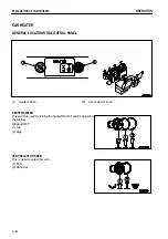
Page 300: ... the same as the standard specification machine so see the manual for the standard specification machine for details EXPLANATION OF COMPONENTS PRESSURE CAUTION LAMP This lamp lights up when the pressurizing pressure in the hydraulic tank goes down If it lights up check that the pressurizing valve is closed and that the pressurizing piping is not is disconnected If the body is raised to near the ma...

Page 301: ...ELEMENT PAGE 4 60 CHANGE OIL IN STEERING HOIST OIL TANK PAGE 4 63 CHANGE OIL IN REAR BRAKE COOLING OIL TANK PAGE 4 64 1 Pull pressurizing valve 1 to shut off the pressure coming from the air tank 2 After shutting off the pressure coming from the air tank turn the oil filler slowly and remove it 3 After carrying out the procedure in Steps 1 and 2 change the oil 4 Return pressurizing valve 1 to its ...

Page 302: ...the adjustment INSTALLING PRESSURE GAUGE 1 Stop the engine and close the pressurizing valve 1 2 To avoid high pressure from being applied to the hydraulic tank turn the knob 2 of the pressure reducingvalve fully in the clockwise direction 3 Pull the ring of drain valve 3 and release the air from the air tank 4 Remove plug 4 of the pressure reducing valve then install the pressure gauge Use a press...

Page 303: ...l go down 5 Operate the dump lever to the FLOAT position and lower the dump body slowly With this operation the indicator on the pressure gauge will go up to a point where the air is discharged from the quick relief valve and the rise in pressure stops 6 Repeat the procedure in Steps 4 and 5 2 to 3 times and seat in the dump body The value indicated by the pressure gauge when the dump body is seat...

Page 304: ...TION OF COMPONENTS 3 5 EXPLANATION OF COMPONENTS 7 2 F FOREWORD 1 2 FUSES 3 36 G GENERAL PRECAUTIONS 2 10 GENERAL VIEW 3 2 GENERAL VIEW OF CONTROLS AND GAUGES 3 3 GENERAL VIEW OF MACHINE 3 2 GUIDES TO MAINTENANCE 4 2 H HANDLING AUTO GREASING SYSTEM 6 45 METHOD OF OPERATING AUTO GREASING SYSTEM 6 47 PRECAUTIONS WHEN HANDLING AUTO GREASING SYSTEM 6 48 HANDLING OIL FUEL COOLANT AND PERFORMING OIL CLI...

Page 305: ...ITH TIRES 2 32 R RECOMMENDED FUEL COOLANT AND LUBRICANT 4 9 RECOMMENDED BRANDS RECOMMENDED QUALITY FOR PRODUCTS OTHER THAN KOMATSU GENUINE OIL 4 11 REVO TACHOGRAPH TCO 15 7 6 17 EXPLANATION OF COMPONENTS 6 17 METHOD OF USE 6 19 S SAFETY CRITICAL PARTS 4 14 SAFETY INFORMATION 1 5 SAFETY INFORMATION 2 2 SAFETY LABELS 2 4 SAFETY PIN 3 35 SERVICE PROCEDURE 4 18 CHECK BEFORE STARTING 4 36 EVERY 100 HOU...

Page 306: ...04 AFTER RUNNING OUT OF FUEL 3 104 IF BATTERY IS DISCHARGED 3 109 METHOD OF TOWING MACHINE 3 104 OTHER TROUBLE 3 113 U USING DIFFERENTIAL LOCK 6 21 DIFFERENTIAL LOCK PEDAL 6 21 PRECAUTIONS AND METHOD OF USE 6 22 W WEAR PARTS 4 8 WEAR PARTS LIST 4 8 8 3 ...

Page 307: ... HD785 5 DUMP TRUCK Form No PEN00042 03 2006 KOMATSU All Rights Reserved Printed in Japan 04 06 ...

Reviews: