Komatsu D375A-8 Operation & Maintenance Manual Download Page 90

ECO GUIDANCE

The  guidance  for  energy  saving  operation  to  reduce  the  fuel
consumption may be displayed during operation.
The details of the guidance are as follows:

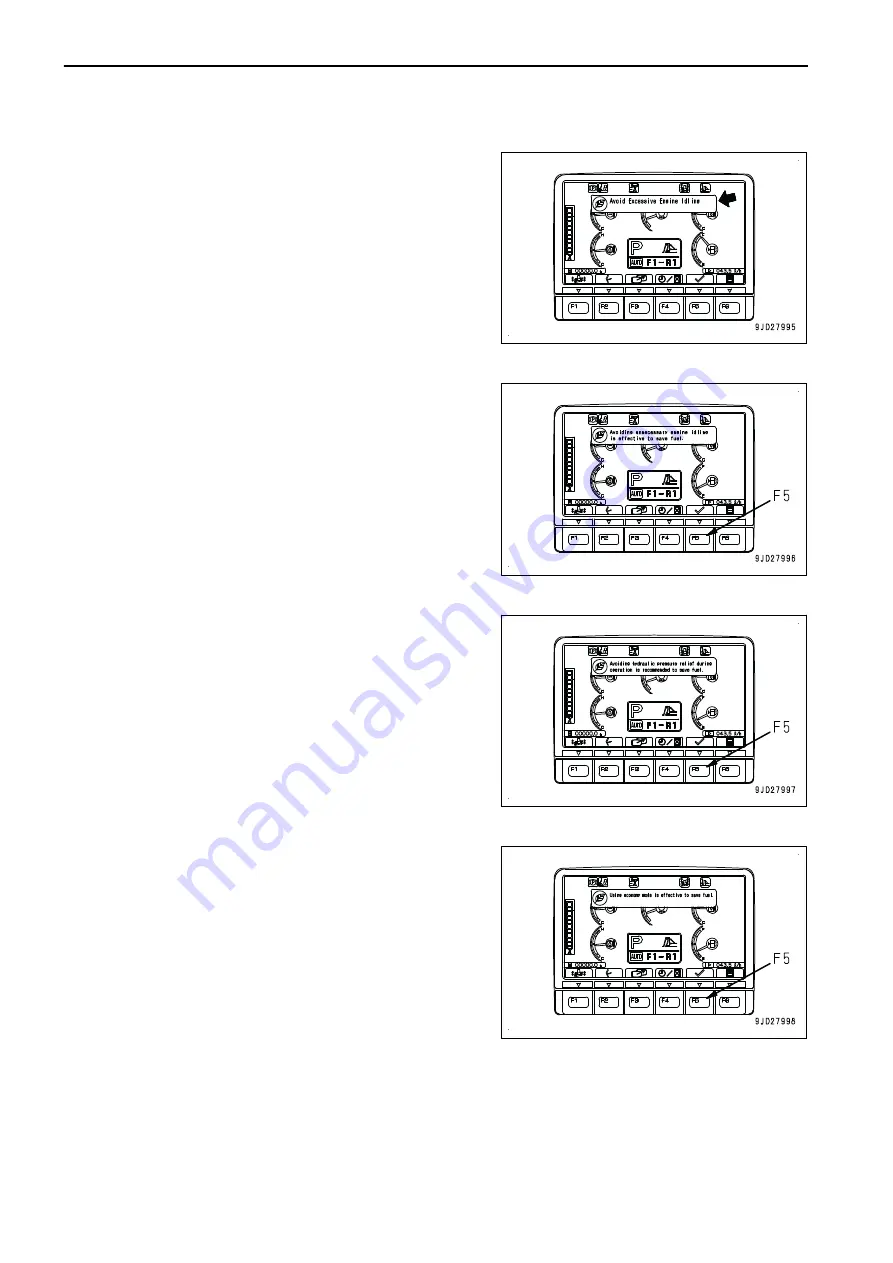
Idling Stop Guidance

If no operation is performed for more than 5 minutes, and the
engine  is  idling,  the  idling  stop  message  is  displayed  on  the
machine monitor. When waiting for work or taking short break,
stop the engine to reduce unnecessary fuel consumption.
The idling stop guidance goes out if any lever is operated again
or switch F5 is pressed.

Guidance To Avoid Hydraulic Relief

If  the  hydraulic  oil  is  kept  relieved  for  more  than  10  seconds
during  operation,  the  hydraulic  relief  deterrence  message  is
displayed on the machine monitor.
The  hydraulic  relief  deterrence  message  goes  out  5  seconds
later or when switch F5 is pressed.

E Mode Recommendation Guidance

If  light-load  work  is  continued  for  more  than  10  minutes  in  P
mode,  E  mode  recommendation  message  is  displayed.  When
working  on  light  load,  set  the  operation  mode  to  E  to  reduce
unnecessary fuel consumption.
E mode recommendation guidance goes out more than 5 sec-
onds after or when switch F5 is pressed.

EXPLANATION OF COMPONENTS

OPERATION

3-32

Summary of Contents for D375A-8

Page 1: ...perators and maintenance personnel must read this manual before operating or maintaining this machine This manual should be kept inside the cab for reference and periodically reviewed by all personnel...

Page 2: ......

Page 3: ...uine new Komatsu or Ko matsu approved rebuilt parts or assemblies or others parts of equivalent quality and that the engine be serviced by an authorized Komatsu distribu tor Failure to follow these re...

Page 4: ...enance Manual Storing Place It is provided on the back side of the operator s seat back If this manual is lost or damaged contact Komatsu or your Komatsu distributor and tell them about the machine mo...

Page 5: ...ng the processing of your personal data i e storage collection transfer etc of all information that relates to you as operator to the party with whom you have most direct relationship In principle thi...

Page 6: ...tion 4 above For the purposes a to l as indicated in section 4 above as well as for the purpose of informing a third party in the context of a possible merger acquisition or demerger the processing of...

Page 7: ...t data b the processing is illegitimate or c the data are no longer needed for the pur poses which are outlined above but you need them to defend yourself in judicial proceedings You have the right to...

Page 8: ...safety mes sage This signal word indicates an imminently hazardous situation which if not avoided will result in death or serious injury This signal word indicates a potentially hazardous situation wh...

Page 9: ...at the operator s station measured according to ISO 6396 Dynamic test method simulated working cycle The maximum value of the standard deviation of the meas ured time averaged A weighted emission soun...

Page 10: ...ic system and linkages 3 Keep the terrain where the machine is working and travelling in good condition Remove any large rocks or obstacles Fill any ditches and holes Site manager should provide machi...

Page 11: ...Do not repeatedly handle and lift loads FOREWORD VIBRATION LEVELS 1 9...

Page 12: ...of travel front of the machine 1 Operator s seat A Front B Rear C Left D Right VISIBILITY FROM OPERATOR S SEAT Risk assessment has been carried out based on the visibility standard ISO5006 and necess...

Page 13: ...Scale interval of the circles is 1 m FOREWORD INTRODUCTION 1 11...

Page 14: ...in North America Komatsu Diesel Particulate Filter KDPF A device which captures diesel particular matter or soot in the exhaust gas to purify exhaust gas f soot is accumulated to a certain level in t...

Page 15: ...ICATION NUMBER PIN MACHINE SERI AL NO PLATE This is under the front of the console box on the right side of the operator s seat The design of the nameplate varies according to the district LOCATION OF...

Page 16: ...of the engine in view of the fan side EPA Environmental Protection Agency USA LOCATION OF BLADE SERIAL NO PLATE This is at the upper right of the blade back face FLUORINATED GREENHOUSE GASES Product...

Page 17: ...OPS PLATE ROPS plate It is on the left side of ROPS FOPS plate It is on the left side of cab SERVICE METER LOCATION This is displayed on the machine monitor YOUR MACHINE SERIAL NUMBERS AND DISTRIBUTOR...

Page 18: ...8414 Japan Serial number B60001 and up Komatsu do Brazil Rodovia ndio Tibiri 2000 Suzano SP CEP 08655 000 Brazil Authorised representative Address KOMATSU EUROPE INT Mechelsesteenweg 586 B 1800 Vilvo...

Page 19: ...B D F G H EI000001 A MACHINE DESIGNATION TYPE E ENGINE POWER B SERIAL NUMBER F PRODUCT IDENTIFICATION NUMBER C YEAR OF CONSTRUCTION G MANUFACTURER D OPERATING MASS H AUTHORISED REPRESENTATIVE FOREWORD...

Page 20: ...SU EUROPE INT Mechelsesteenweg 586 B 1800 Vilvoorde Belgium Declares that this machine D375A 8 Fulfils all the relevant provisions of following EC Directives Machinery Directive 2006 42 EC Electro Mag...

Page 21: ...ELS 2 3 CONTENTS OF SAFETY LABELS 2 4 GENERAL PRECAUTIONS COMMON TO OPERATION AND MAINTENANCE 2 10 PRECAUTIONS BEFORE STARTING OPERATION 2 10 PREPARATIONS FOR SAFE OPERATION 2 10 PRECAUTIONS TO PREVEN...

Page 22: ...PARKING MACHINE 3 207 METHOD FOR CHECKING AFTER FINISHING WORK 3 208 LOCK 3 209 HANDLE AIR CONDITIONER 3 212 EXPLANATION OF AIR CONDITIONER EQUIPMENT 3 213 METHOD FOR OPERATING AIR CONDITIONER 3 217...

Page 23: ...HOURS 4 15 WHEN REQUIRED 4 15 CHECKS BEFORE STARTING 4 46 EVERY 250 HOURS MAINTENANCE 4 47 EVERY 500 HOURS MAINTENANCE 4 51 EVERY 1000 HOURS MAINTENANCE 4 57 EVERY 2000 HOURS MAINTENANCE 4 66 EVERY 4...

Page 24: ...nalysis 6 31 WHEN REQUIRED 6 32 EVERY 250 HOURS MAINTENANCE 6 35 EVERY 500 HOURS MAINTENANCE 6 37 EVERY 1000 HOURS MAINTENANCE 6 39 EVERY 2000 HOURS MAINTENANCE 6 44 CONSUMABLE PARTS 6 49 REPLACEMENT...

Page 25: ...se read and make sure that you fully understand the precautions descri bed in this manual and the safety labels on the machine When operating or servicing the machine always follow these precautions s...

Page 26: ...ly When cleaning the safety labels do not use organic solvents or gasoline These may cause the labels to peel off If the safety labels are damaged lost or cannot be read properly replace them with new...

Page 27: ...re hydraulic oil 7 Caution for check and adjust track tension 8 Caution for battery cable 9 Caution for engine running 10 Caution for handling accumulator 11 Caution for use of seat belt 12 Caution fo...

Page 28: ...tion To prevents SEVERE INJURY or DEATH do the following be foremoving machine or its attachments Honk horn to alert people nearby Be sure no one is on or near machine or in swing area Use spotter if...

Page 29: ...ng up from the radiator or hydraulic tank will cause personal injury and or burns Never remove the radiator cap or hydraulic tank oil filler when cooling water or hydraulic oil is at high temperatures...

Page 30: ...on for battery cable 09808 A0881 Sign indicates an electric hazard from handling the cable Read manual for safe and proper handling Caution for engine running 09667 A0481 Sign indicates a hazard of ro...

Page 31: ...modification is prohibited ROPS may provide less protection if it has been structurally damaged or involved roll over Consult Komat su Distributor in that case Always wear seat belt when moving Cautio...

Page 32: ...operator s seat Do not attempt to start the engine by shot circuiting the en gine starting circuit Such an act may cause a serious bodi ly injury or fire Caution for blast site only when equipped with...

Page 33: ...Caution for not getting on fuel tank 09805 C0641 Sign indicates a hazard of falling Do not stand on this place here 09805 C0641 SAFETY SAFETY LABELS 2 9...

Page 34: ...r explanation PREPARATIONS FOR SAFE OPERATION PRECAUTIONS FOR SAFETY RELATED EQUIPMENT Be sure that all guards covers cameras and mirrors are in their proper position Repair them immediately if they a...

Page 35: ...re Do not use a cellular phone when driving or operating the machine This may lead to mistakes in operation and may cause serious personal injury or death Never bring any dangerous objects such as fla...

Page 36: ...in the specified place and do not allow unauthorized persons to enter When performing grinding or welding work on the machine move any flammable materials to a safe place before starting Fire caused...

Page 37: ...filling the tank with oil Never use them when getting on or off the machine Always face the machine and maintain at least three point contact both feet and one hand or both hands and one foot with th...

Page 38: ...are not taken when parking the machine the machine may suddenly move off by itself and this may lead to serious personal injury or death Always observe the following When leaving the machine always lo...

Page 39: ...d in any other way its strength may drop Any modification is prohibited If the protective structure is damaged or deformed by falling objects or by rolling over its strength will be reduced and it wil...

Page 40: ...rt or operate the engine in a place where there is good ventilation If the engine or ma chine must be operated inside a building or underground where the ventilation is poor take steps to ensure that...

Page 41: ...truct travel PRECAUTIONS WHEN WORKING ON LOOSE GROUND Avoid driving or operating the machine near the edge of cliffs road edges and deep ditches The ground may be weak in such areas If the ground shou...

Page 42: ...and set up additional lighting in the work area if necessary Stop operations if the visibility is poor because of mist snow rain or dust When checking the mirrors installed to the machine remove all d...

Page 43: ...to ensure that there is no problem with the operation of the machine If these checks are not performed properly problems may occur with the operation of the machine and there is a danger which may le...

Page 44: ...t may not be what the operator intended Be sure to perform the warm up operation Particularly in a cold weather be sure the warming up operation is completed If the battery electrolyte is frozen do no...

Page 45: ...of scattering fragments and things which may intrude into operator s cab Prohibit other personnel to get on the machine If there are any persons in the area around the machine there is danger that th...

Page 46: ...during the travel PRECAUTIONS WHEN TRAVELING ON SLOPES To prevent the machine from tipping over or slipping to the side always observe the following Never turn the key in the starting switch to OFF p...

Page 47: ...e not able to es cape Be particularly careful when working on frozen road It is dangerous that the machine enters deep snow The machine may tip over or become buried in the snow Be careful not to go o...

Page 48: ...s of adequate strength Be sure that the ramps are wide long and thick enough to provide a safe loading slope Take suitable steps to prevent the ramps from moving out of position or coming off 1 Chocks...

Page 49: ...s confirm that the wire rope or drawbar used for towing has ample strength for the weight of the ma chine being towed Never use the wire rope which has cut strands A re duced diameter B or kinks C The...

Page 50: ...e clean the tidy to enable you to perform operations safely If the work place is not kept clean and tidy there is the danger that you will trip slip or fall over and injure your self SELECT SUITABLE P...

Page 51: ...osition set work equip ment lock lever 1 to FREE position F operate the work equipment control lever to RAISE and LOWER position a few times repeatedly to release the remaining pressure in the hydraul...

Page 52: ...o that they do not fall And take steps to prevent unauthorized persons from entering the storage area PRECAUTIONS FOR WORKING AT HIGH PLACES When working at high places use a step ladder or other stan...

Page 53: ...the work equipment and machine are not supported they may come down and it may cause serious per sonal injury or death Never use concrete blocks for supports Concrete blocks may break under even ligh...

Page 54: ...lphuric acid Any mistake in handling may cause serious personal injury explosion or fire Always ob serve the following When handling the battery always wear protective eye glasses and rubber gloves If...

Page 55: ...cap or plug slowly to release the internal pressure and remove the cap or plug PRECAUTIONS FOR HIGH TEMPERATURE PARTS To prevent burns from touching high temperature parts when checking or performing...

Page 56: ...loose or oil or fuel is found to be leaking from the mount stop operations and tighten to the specified torque If any damaged or deformed hoses or piping are found consult your Komatsu distributor Rep...

Page 57: ...njury or death If it is necessary to disassemble it ask your Komatsu distributor to perform the work ACCUMULATOR AND GAS SPRING This machine is equipped with an accumulator Even after the engine stops...

Page 58: ...es Obey appropriate laws and regulations when disposing of harmful objects such as oil fuel coolant solvent filters batteries and DEF Avoid exposure to burning rubber or plastics which produce a toxic...

Page 59: ...OPERATION Please read and make sure that you understand the SAFETY section before reading this section 3 1...

Page 60: ...GENERAL VIEW MACHINE EQUIPMENT NAME 1 Blade 2 Blade lift cylinder 3 Cab 4 ROPS 5 Fuel tank 6 Ripper 7 Track 8 Sprocket 9 Track frame 10 Frame GENERAL VIEW OPERATION 3 2...

Page 61: ...9 Engine room light switch if equipped 10 Rear lamp switch 11 Head lamp working lamp switch 12 Machine monitor 13 Starting switch 14 Engine shutdown secondary switch 15 Additional working lamp switch...

Page 62: ...s Regeneration disable pilot lamp 14 Message display 15 Operation mode pilot lamp 16 Air conditioner pilot lamp 17 Preheating pilot lamp 18 Fan reverse pilot lamp 19 Reverse travel slow mode pilot lam...

Page 63: ...REMARK The above figure does not show all of the caution lamp symbols OPERATION GENERAL VIEW 3 5...

Page 64: ...QUIPMENT AA Standard screen EE Warning or Error screen DD Guidance screen 1 Warning display 2 Meter display 3 Gear speed display part 4 Monitor switch area 5 Guidance display 6 Guidance icon display 7...

Page 65: ...ng screen BB After the check before starting screen BB is displayed for 2 seconds the screen switches to the preset starting gear speed display screen HH After the preset speed range when moving machi...

Page 66: ...ayed and engine does not start If engine shutdown secondary switch 1 is turned OFF nor mal the machine monitor switches to the standard screen and you can start the engine with usual starting switch k...

Page 67: ...starting screen GG switches to the ID number input screen LL with SKIP when the starting switch is turned to ON position When the operator identification function is effective and without SKIP is set...

Page 68: ...e displayed while the starting switch is turned to ON position If the incorrect ID number is inputted for 3 times in a row you cannot input the ID number in the next 5 minutes Wait for more than 5 min...

Page 69: ...efore starting screen BB for 2 seconds the screen changes to the mainte nance time warning screen CC After displaying the maintenance time warning screen CC for 30 seconds the screen returns to the st...

Page 70: ...Current Abnormality screen is displayed BASIC OPERATION OF MACHINE MONITOR WHEN TROUBLE OCCURS WHILE OPERATING MACHINE If any abnormality occurs during operation the standard screen AA changes to the...

Page 71: ...aution lamp that lights up in red when an action level is displayed warns operator to stop the ma chine urgently stop or pause the current operation If no action is taken the machine can be seriously...

Page 72: ...ons are generated they are sequentially displayed starting from the leftmost side of the screen ACTION LEVEL DISPLAY Action level display 1 indicates the degree of urgency of the abnormalities current...

Page 73: ...These caution lamps do not guarantee the condition of the machine Do not simply rely on the caution lamp when performing the checks before starting start up inspec tion Always get off the machine and...

Page 74: ...Abnormal L04 L03 Abnormal L01 Transmission system caution lamp Abnormal L04 L03 Abnormal L01 KDPF system caution lamp Abnormal L04 L03 Abnormal L01 KDPF soot accumulation caution lamp Abnormal L03 Ac...

Page 75: ...tion lamp Abnormal L01 Seat belt caution lamp Seat belt un fastened Maintenance time caution lamp Due time is over Notice Engine oil level caution lamp Low oil level L01 Hydraulic oil level caution la...

Page 76: ...iate remedies according to the displayed mes sage Operation on the Current Abnormality screen On the Current Abnormality screen you can perform the follow ing operations with switches F1 F2 and F5 F1...

Page 77: ...s up in red and indicates action level L02 The power train oil temperature has risen abnormally high While this lamp is lit the overheat prevention system is auto matically actuated and the engine spe...

Page 78: ...nctions may be restricted for use but the machine can operate When you finish the operation always perform the inspection and maintenance Ask your Komatsu distributor for inspection and maintenance as...

Page 79: ...em When action level L04 is displayed The caution lamp lights up in red and the alarm buzzer sounds continuously Stop the machine immediately and ask your Komatsu distribu tor for inspection and maint...

Page 80: ...then ask your Komatsu distributor for inspection and maintenance When action level L01 is displayed The caution lamp lights up in yellow Some functions may be restricted for use but the machine can op...

Page 81: ...ays perform the inspection and maintenance Ask your Komatsu distributor for inspection and maintenance as needed TRANSMISSION OIL FILTER CLOGGING CAUTION LAMP The transmission oil filter clogging caut...

Page 82: ...n action level L03 is displayed The caution lamp lights up in red and the alarm buzzer sounds intermittently Stop the work move the machine to a safe place and then ask your Komatsu distributor for in...

Page 83: ...iator coolant level caution lamp warns about drop of radia tor coolant level When the coolant level dropped The caution lamp lights up in yellow and indicates action level L01 The radiator coolant is...

Page 84: ...y Ask your Komatsu distributor for inspection and maintenance as soon as possible MAINTENANCE TIME CAUTION LAMP Maintenance time caution lamp displays notices and alarms concerning maintenance time Th...

Page 85: ...stened It goes out when the seat belt is fastened For details of the seat belt see METHOD FOR FASTENING AND UNFASTENING SEAT BELT HYDRAULIC OIL LEVEL CAUTION LAMP if equipped The hydraulic oil level c...

Page 86: ...p 11 Fan reverse rotation pilot lamp 12 Reverse travel slow mode pilot lamp 13 Dual tilt mode pilot lamp 14 Floating mode pilot lamp 15 Blade fine control mode pilot lamp 16 Auto pitch pilot lamp 17 R...

Page 87: ...ilot lamp lights up while the fan is ro tating in reverse For the reverse rotation of the fan see Reverse hydraulic fan AIR CONDITIONER PILOT LAMP The air conditioner pilot lamp shows the operating st...

Page 88: ...REGENERATION PILOT LAMP k k CAUTION Exhaust gas temperature may increase higher than the previous models during the aftertreatment devices regeneration Stay away from the exhaust pipe outlet to preve...

Page 89: ...goes out when the work equipment lock lever is set in FREE position If it is required to set the work equipment lock lever in LOCK position the work equipment lock pilot lamp flashes PARKING BRAKE PIL...

Page 90: ...n or switch F5 is pressed Guidance To Avoid Hydraulic Relief If the hydraulic oil is kept relieved for more than 10 seconds during operation the hydraulic relief deterrence message is displayed on the...

Page 91: ...conds or when switch F5 is pressed Engine stop operation during the aftertreatment devices regeneration guidance Immediately after starting the aftertreatment devices regeneration the information abou...

Page 92: ...n of the customize mode see CUSTOMIZE SWITCH AUTO PITCH PILOT LAMP The auto pitch pilot lamp indicates the operating state of the auto pitch function Change the setting of the function on the customiz...

Page 93: ...d in this case A to B Red range A to C Green range For other items displayed by the multi gauge see METHOD FOR USING MULTI GAUGE ENGINE COOLANT TEMPERATURE GAUGE Engine coolant temperature gauge shows...

Page 94: ...rain oil temperature caution lamp E shows abnormality display and alarm buzzer sounds at the same time The overheat prevention system continues to operate until the indicator enters the green range NO...

Page 95: ...ons When the indicator comes close to A of the red range during operation check and add fuel as necessary A to B Red range A to C Green range REMARK When the indicator is in red ranges A to B fuel lev...

Page 96: ...ge A the instantaneous fuel consumption is at a good to medium level When the gauge is in yellow range B the instantaneous fuel consumption is at a bad level REMARK Although there is no abnormality on...

Page 97: ...ctor switch 3 Buzzer cancel switch 4 Gear shift mode selector switch 5 Work equipment automation switch 6 Customize switch 7 Reverse travel slow mode switch 8 Air conditioner switch FUNCTION SWITCHES...

Page 98: ...tor switch C Switch F3 Camera image selector switch D Switch F4 Service meter clock display selector switch E Switch F5 Current Abnormality list display switch While the caution lamp is displayed F Sw...

Page 99: ...eturns to the previous screen M Switch F6 Accepts any selection and change contents and goes to the next screen REMARK Even if some icons look the same their display positions and corresponding functi...

Page 100: ...CUSTOMIZE SWITCH k k CAUTION To ensure safety always stop the machine before operating the customize mode Press the customize switch and the customize mode selection screen is displayed On the customi...

Page 101: ...ows an example of the setting change screen when the operating mode is selected 3 After changing the setting of each item press the switch F2 The memory saving screen is displayed 4 Check the setting...

Page 102: ...gear shift mode selector switch changes the gear shift mode to automatic gear shift mode manual gear shift mode and shoe slip control mode In the automatic gear shift mode the transmission shifts up a...

Page 103: ...e properly for digging and dozing Since the pitch angle does not need manual control the operator s fatigue is reduced The operator can enable disable this function by using the work equipment automat...

Page 104: ...de is pitched back fully to digging or dozing Q positions dur ing reverse travel even if the operator does not push the auto pitch button If the operator changes the blade pitch angle with the work eq...

Page 105: ...tion is finish ed 2 Auto pitch function stops To start the auto pitch operation again after each operation is finished push auto pitch button P again Digging position set mode While the machine is tra...

Page 106: ...oes not operate when oper ation forward travel is only ripping work Also pitches back fully to digging or dozing Q position when auto pitch button P is pushed 1 Auto pitch function is interrupted Auto...

Page 107: ...urn function has the 3 modes of lift only lift and tilt independent operation lift and tilt interlocked operation which can be set on the Mode Select screen Setting of the ripper auto return function...

Page 108: ...while the ripper auto return function is in operation the manual operation is given priority and the ripper auto re turn function is canceled Gear shifting Ripper raise operation Ripper tilt back oper...

Page 109: ...FT LOWER posi tion c or the tilt control switch is set to TILT IN position A while the ripper auto return function is in operation the manual operation is given priority and the ripper auto return fun...

Page 110: ...l operation is given priority and the ripper auto re turn function is canceled Gear shifting Ripper raise operation Ripper tilt back operation Each operation while ripper auto return function is ON St...

Page 111: ...conditioner control screen When the screen switches to the air conditioner operation screen press switch F6 to return the screen to the camera image In addition if no operation is performed for 5 sec...

Page 112: ...cel switch is pressed the camera image display does not switch to another screen or return to the standard screen Depending on the warning alarm buzzer does not stop sounding by pressing the buzzer ca...

Page 113: ...rmality or warning display While the caution lamp is flashing if no lever is operated for 10 seconds or more the screen automatically returns to the standard screen When the screen returns to the stan...

Page 114: ...yed press switch F4 to switch to the clock display DUAL TILT MODE SWITCH Only machines equipped with dual tilt function When function switch F1 is pressed the dual tilt mode is se lected When it is pr...

Page 115: ...graph 8 Pitch graph 9 Clock display Approximate values indicated by the multi gauge are as follows Engine speed 1 500 rpm 2 1000 rpm 3 1500 rpm 4 2000 rpm 5 2625 rpm 6 3000 rpm Travel speed 1 0 km h...

Page 116: ...e drawbar pull Similarly to the ECO gauge it is recommended to use in green range G The graphs on the screen are updated and scrolled to the left at intervals of several seconds The latest information...

Page 117: ...f the following kinds Press switches F1 and F2 to move to right and left for selecting menu screens a Energy Saving Guidance b Machine Setting c Aftertreatment Devices Regeneration d Maintenance e Mon...

Page 118: ...kip Mode if equiped Set Maximum Engine Speed for R1 Set Maximum Engine Speed for R2 Set Maximum Engine Speed for R3 c Aftertreatment Devices Regeneration Setting for Regeneration Disable Operation of...

Page 119: ...When on the right end menu it moves to the left end menu F3 Moves to the next item 1 line below When on the last line it moves to the first line F4 Moves to the previous item 1 line above When on the...

Page 120: ...Fuel Consump tion Actual Working Fuel Consumption Idling Hours and E mode time ratio on daily basis or on a split measurement peri od basis are displayed Operation on the Operation Records screen On...

Page 121: ...F5 Returns the screen to the Energy Saving Guidance menu screen REMARK ECO guidance denotes displaying the guidance for energy sav ing operation This display may appear on the standard screen while t...

Page 122: ...ayed value of fuel consumption may differ from the actual value due to the operating conditions of the customers fuel weather or work contents etc Switching of displayed graph Press F2 on the Average...

Page 123: ...e Setting the Average Fuel Consumption Display Switching ON OFF of the ECO Gauge Display Setting the ECO Gauge Display Fuel Target Value Switching ON OFF of the ECO Guidance Display Switching ON OFF o...

Page 124: ...ne F4 Moves to the previous item 1 line above When on the first line it moves to the last line F5 Cancels the setting and returns to Configurations screen F6 Changes the setting and returns to Configu...

Page 125: ...reen When you stop the measurement move from Energy Saving Guidance menu a screen to the Operation Records 1 screen or ECO Guidance Records 2 screen then press the measure ment stop switch F1 STOP SWI...

Page 126: ...the setting and returns to Configurations screen F6 Changes the setting and returns to Configurations screen SET TARGET FUEL CONSUMPTION VALUE DISPLAYED IN ECO GAUGE It is possible to change the targe...

Page 127: ...it is possible to perform the following operations with switches F3 to F6 F3 Moves to the next item 1 line below When on the last line it moves to the first line F4 Moves to the previous item 1 line a...

Page 128: ...possible to perform the following oper ations with switches F3 to F6 F3 Moves to the next item 1 line below When on the last line it moves to the first line F4 Moves to the previous item 1 line above...

Page 129: ...engine speed may not increase even if the fuel control dial is set to High idle MAX position but this is not a failure The hydraulic fan reverse mode fan reverse rotation can be used to remove the ins...

Page 130: ...versing operation press the switch F5 10 Since the fan reverse rotation is set start the engine After the engine is started the machine monitor screen displays as shown in the figure If the parking br...

Page 131: ...nditions are satisfied The engine is running normally The parking brake lever and work equipment lock lever are in LOCK positions The engine coolant temperature hydraulic oil temperature and power tra...

Page 132: ...down stops and the screen returns to the standard screen 4 When countdown reaches 0 the engine stops and the screen changes to the Auto Idle Stop in Operation screen 5 To prevent battery discharging t...

Page 133: ...Maximum Engine Speed for R1 Set Maximum Engine Speed for R2 and Set Maximum Engine Speed for R3 the maximum engine speed at traveling in reverse can be set 1 Select Set Maximum Engine Speed for R1 on...

Page 134: ...Change 1000 P T Oil Change 1000 P T Case Breather Change 1000 Final Drive Oil Change 2000 Hydraulic Oil Pilot Filter Change 1000 Fuel Tank Breather Change 1000 Hydraulic Oil Filter Change 2000 Damper...

Page 135: ...lighted in red If you want to change the setting for the maintenance time or maintenance notice time initial setting 30 hours consult your Komatsu distributor Operations on the Maintenance Due Time Re...

Page 136: ...the Monitor Set ting menu screen F6 Accepts the change and returns to the Monitor Set ting menu screen REMARK If the light switch is at night mode ON and the screen is adjusted it is possible to adju...

Page 137: ...en can be set Camera image screen brightness adjustment Camera view mode setting Setting of Reverse Synchroni zation Guide line display mode setting On this screen it is possible to perform the follow...

Page 138: ...ent Cam era menu 2 Press switch F6 3 The Camera View Mode setting screen is displayed Normal Switch F2 of the function key is used to change the screen to the camera screen Reverse Synchronization Cam...

Page 139: ...it is possible to perform the following operations with switches F3 to F6 F3 Moves to the next item 1 line below When on the last line it moves to the first line F4 Moves to the previous item 1 line a...

Page 140: ...and time in accordance with the clock of GPS F3 Moves to the next item 1 line below Moves to the top line when on the bottom line F4 Moves to the previous item 1 line above Moves to the bottom line w...

Page 141: ...6 F3 Calendar goes back 1 month F4 Calendar advances 1 month F5 Cancels change and returns to the year setting screen F6 Proceeds to setting for date 4 When date display C is highlighted in yellow ope...

Page 142: ...epts change and returns the screen to Clock Ad justment screen SWITCH 12H 24H DISPLAY MODE Choose either a 12 hour display AM PM or a 24 hour display 24 hour system display 12 hour system display AM P...

Page 143: ...possible to select the language used on the monitor display The languages that can be selected are as follows English Japanese French Spanish Portuguese Italian German Swedish Dutch Danish Norwegian...

Page 144: ...on function WHEN OPERATOR IDENTIFICATION FUNCTION IS AVAILABLE WITH SKIP When the starting switch is ON and ID is inputted the identified ID is displayed in the column of Operator ID on the Monitor Se...

Page 145: ...D is not identified When you press switch F6 after inputting the ID which is not registered to the Operator ID Change screen a message is displayed below and the screen returns to the Monitor Setting...

Page 146: ...etting menu screen In this case the identified ID is not changed On the Operator ID Change screen if no switch is operated for more than 30 seconds the screen auto matically changes to the Monitor Set...

Page 147: ...essage the message display lights up in blue B The message will be deleted when it becomes out of date or when a new message arrives CHECK MESSAGE 1 Press switch F6 on the standard screen When there i...

Page 148: ...dis played in the column 1 of the mail confirmation menu screen press switch F6 again The input value will be sent out When the message Do you send Numeric Input is dis played if you press switch F5 t...

Page 149: ...tarts When the preheat pilot lamp changes from lighting to flashing release the key immediately When the switch is released it automatically returns to OFF position A Turn the starting switch key to S...

Page 150: ...al caught in arm or blade Snow or ice sticking to arm or blade This is also used as the window washer switch The switch is operated as follows Switches LH FF RH and RR a ON position The wiper operates...

Page 151: ...lack D For front colorless E Washer tube tank side F Washer tube cab side G Left door blue H Right door red I Rear window black J Front window colorless HORN SWITCH If you press the horn switch the ho...

Page 152: ...ear lamp goes out PIN PULLER OPERATION SWITCH if equipped only for the machine equipped with giant ripper The pin puller operation switch is used to operate the ripper shank pin A Pull The pin is pull...

Page 153: ...SWITCH if equipped By turning the engine emergency shut down switch to ON posi tion A the engine stops in emergency ON position A Engine stops in emergency OFF position B Engine can be started REMARK...

Page 154: ...lt your Komatsu distributor ADDITIONAL WORKING LAMP SWITCH if equipped The additional working lamp switch is used to turn on or off the additional working lamps A Front additional working lamp B Rear...

Page 155: ...ess light ENGINE ROOM LIGHT SWITCH if equipped Engine room light is turned on with the engine room light switch A Engine room light REVOLVING LAMP SWITCH if equipped OPERATION EXPLANATION OF COMPONENT...

Page 156: ...the breaker switch C to operate the console lifter switch again ENGINE SHUTDOWN SECONDARY SWITCH NOTICE The engine shutdown secondary switch is used to stop the engine when the starting switch is tur...

Page 157: ...is closed the engine shutdown secondary switch automatically returns to the NOR MAL position b When the starting switch is turned to ON position while the engine shutdown secondary switch is in the S...

Page 158: ...th single tilt This mode is used for lifting and tilting the blade Lifting control a RAISE b HOLD Blade is held at current position c LOWER d FLOAT button Blade is moved freely by external force REMAR...

Page 159: ...is not lit the machine is set in the single tilt mode Lifting control a RAISE b HOLD Blade is held at current position c LOWER d FLOAT button Blade is moved freely by external force p Pitch switch REM...

Page 160: ...mp M is not lit Pitching control Reverse pitch blade edge angle is small Set pitch switch p toward E Forward pitch blade edge angle is large Set pitch switch p toward D Auto pitch Auto pitch is a func...

Page 161: ...in LOCK position se curely the parking brake may not be locked Check that the parking brake lever is under the state in the figure When leaving the machine be sure to set the parking brake lever to L...

Page 162: ...ver The work equipment lock lever is a locking device of the blade control lever and the ripper control lever When operating the work equipment lock lever always use the control lever Do not operate b...

Page 163: ...stick steering directional and gear shift lever is in FORWARD or REVERSE position up switch c The gear is shifted up by 1 step each time this switch is pressed down switch d The gear is shifted down b...

Page 164: ...depress the decelerator pedal to reduce the travel speed in advance RIPPER CONTROL LEVER The ripper control lever is used for operating the ripper a RAISE b HOLD Ripper is stopped and held in this po...

Page 165: ...catch 1 The door is fixed to the catch 2 When releasing the door move lever 2 in the cab toward the front inside the cab The catch releases NOTICE When keeping the door open fix it securely to the ca...

Page 166: ...sition CAP AND COVER WITH LOCK Use the starting switch key to open and close the locks on the caps and covers Insert the key as far as it will go to the shoulder A and turn it If the key is turned whe...

Page 167: ...ously NOTICE When connecting the devices to the power supply of the type which can be used continuously turn off the power supply manually Otherwise it may cause the dead battery FUSE NOTICE Before re...

Page 168: ...System operating lamp 8 5 A Key ACC engine 9 5 A Key ACC air conditioner 10 20 A Key ACC spare 11 15 A Fuel feed pump P 12 15 A Fuel feed pump C 13 5 A DPF temperature sensor power supply P 14 5 A DP...

Page 169: ...it turn the starting switch to OFF position and push in the reset button which projected when the circuit was cut out The reset button remains pushed in if the electrical circuit is operating normally...

Page 170: ...To restore the cut out electrical circuit wait for 5 to 10 mi nutes after it has been cut out and push the reset button If the electrical circuit is cut out the operating effort of the reset button is...

Page 171: ...battery disconnect switch only when the engine is stopped NOTICE Keep the battery disconnect switch in ON position except the following cases When the machine is stored for a long time more than a mo...

Page 172: ...een when the controller is turned ON Usually it goes out in 5 to 6 minutes after the starting switch is turned to OFF position Before operating the battery disconnect switch check that lamp 1 is not l...

Page 173: ...vices Regeneration the Aftertreatment Devices Regeneration pilot lamp 1 stays lit on the machine monitor REMARK Even if the Aftertreatment Devices Regeneration pilot lamp 1 lights up the machine does...

Page 174: ...top engine When the Action level L03 lights up in red and the KDPF soot accumulation caution lamp 2 lights up in red engine power deration is activated To restore engine power it is necessary to perfo...

Page 175: ...e matter which cannot be burnt by the regeneration is accumulated in the filter of KDPF the filter needs to be cleaned or replaced at regular intervals The engine speed or engine sound may change duri...

Page 176: ...oot accumulation caution lamp 2 lights up in yellow stop the machine in a safe place after finishing the operation and perform the manual stationary regeneration When the degree of emergency is high K...

Page 177: ...th engine running 2 Check that there is no person or combustible matter around the machine particularly in the direction of the ex haust gas flow 3 Set the parking brake lever and work equipment lock...

Page 178: ...DPF soot accumulation caution lamp is lit the accumulat ed soot may not be burnt sufficiently and the filtering func tion may not be improved Wait until the Aftertreatment De vices Regeneration pilot...

Page 179: ...ne monitor during this regeneration It is completed in approxi mately 10 minutes If the parking brake lever and work equipment lock lever or the fuel control dial is operated during the manual station...

Page 180: ...it may cause the failure of KDPF or the engine While regeneration is not being performed Setting for the regeneration disable When the aftertreatment devices regeneration pilot lamp is lit on the sta...

Page 181: ...amp 3 may light up but this does not indi cate abnormality Also during the regeneration to protect the system the regeneration disable cannot be operated When the regeneration is performed to protect...

Page 182: ...ices Regeneration screen is displayed If the screen is not displayed operate switch F1 and F2 and display the Aftertreatment Devices Regeneration screen 2 Select the Cancel of the regeneration disable...

Page 183: ...s of KOMTRAX consult your Komatsu distributor If the machine has been lent out by the customer the borrower or another third party may have been using the KOMTRAX Confirm with the lessor about using c...

Page 184: ...nding on the machine For the radio sta tion establishment of KOMTRAX Plus consult your Komatsu distributor POWER SUPPLY FOR KOMTRAX Plus Even when the key in the starting switch of the KOMTRAX Plus sy...

Page 185: ...r play in work equipment cylinders linkage and hoses If any problem is found repair it 2 Remove dirt and debris from around the engine battery and radiator Check for dirt accumulated around the engine...

Page 186: ...place or take an unstable posture you may fall and be injured Put proper stepladder or step on the level and firm ground and clean the camera in secure posture Check the camera for any abnormality If...

Page 187: ...ain them ac cording to the following procedure 1 Place a container to receive the water under the drain hose 3 2 Loosen the plug 4 and drain the water 3 When a certain amount of water and sediment in...

Page 188: ...r b to the ground with the pin at the bot tom so that the shank is vertical For the length of each cylinder see the following table Reference Item Dimension Blade DUAL Tilt cylinder length 1587 mm Bla...

Page 189: ...is below L level add oil through the oil filler port F NOTICE Do not add it above H level This will cause the oil to spurt out If oil has been added to above H level stop the engine and wait for the...

Page 190: ...ETHOD FOR CHECKING AND REPLACING RADIATOR CAP AND PRESSURE CAP If the reservoir tank is empty in a short time after adding coolant leakage of coolant should be suspect ed After checking repair any abn...

Page 191: ...ulated in the radiator You may get burn injury if you open the pressure cap 6 in this state Always wait for the temperature to go down and turn the pressure cap 6 slowly to release the pressure then r...

Page 192: ...move the drain plug 1 loosen the drain valve 2 and drain the excessive oil 2 After draining the oil tighten the drain valve 2 3 Install the drain plug 1 and check the oil level again 7 If the oil leve...

Page 193: ...hile the engine is running or after running the engine check it by HOT IDLE side of the dipstick G with the engine running at low idle 6 If the oil level is below L mark add oil through the oil filler...

Page 194: ...t sunlight sandy district etc replace it before reading becomes difficult because of dirt METHOD FOR CHECKING BRAKE OPERATION 1 Drive the machine in FORWARD 2nd speed range 2 Depress the brake pedal a...

Page 195: ...l gauge pointer reads the red range the fuel quantity is 250 or less When the fuel level is low add fuel 3 After checking turn the starting switch back to OFF posi tion 4 Check that the engine is stop...

Page 196: ...lb or disconnected wire are the possible causes Ask your Komatsu distributor for repairs 4 After finishing the check turn the head lamp to OFF posi tion c and turn the rear lamp to OFF position e 5 Tu...

Page 197: ...SIT IN ENGINE COMPARTMENT Check that there is no deposit inside the engine compartment particularly around the turbocharger exhaust manifold and aftertreatment devices If there is any deposit remove i...

Page 198: ...ADJUSTING OPERATOR S SEAT k k WARNING When adjusting the position of the operator s seat always set the work equipment lock lever and parking brake lever to LOCK positions to prevent any accidental co...

Page 199: ...smaller as the seat is moved backward When moving the seat backward return the reclined seat back to the original position 1 Pull up the reclining adjustment lever 2 and set the seat back to a positio...

Page 200: ...ed for the adjustment NOTICE Do not operate the switch continuously for 1 minute or longer Doing so can damage the air compres sor The seat height is adjusted pneumatically and in stepless 1 Adjust th...

Page 201: ...air compressor built in the seat is used 1 Turn the starting switch to ON position and perform the adjustment 2 Operate the air lumbar support switch 6 A proper tension can be given to the waist part...

Page 202: ...tion c The damper becomes softer METHOD FOR HEATING SEAT k k CAUTION Using the heater for a long time may cause low temperature burn blister etc Do not put a heavy luggage on the cushion Do not stick...

Page 203: ...G SEAT VENTILATION k k CAUTION Do not put heavy luggage on the cushion Do not stick the cushion with needles nails etc If water or beverage etc spills on the seat cushion wipe it off with soft cloth e...

Page 204: ...operator s seat In particular adjust so that you can see persons at the rear ends of the right and left sides of the machine METHOD FOR ADJUSTING JOYSTICK STEERING DIRECTIONAL AND GEAR SHIFT LEVER PCC...

Page 205: ...s seat can be adjusted in height as shown below After adjusting the operator s seat adjust them to proper height METHOD FOR ADJUSTING RIGHT ARMREST R H armrest 1 can be adjusted to 20 mm and 40 mm ab...

Page 206: ...in the belt replace the seat belt every 3 years from starting usage or 5 years after manufacture whichever comes sooner Be sure to use the seat belt during operation Do not twist the seat belt when f...

Page 207: ...ckle 4 securely Fasten the seat belt without twisting along your body 3 Pull the belt lightly to check that it is properly locked If the tongue is not inserted in the buckle the seat belt caution lamp...

Page 208: ...ng brake lever 1 and work equipment lock lever 5 to the LOCK positions whether the engine is running or stopped 1 Check that battery disconnect switch S is in ON position I 2 Check that parking brake...

Page 209: ...heck that blade control lever 3 is in HOLD position b 5 Check that ripper control lever 4 is in HOLD position b 6 Check that work equipment lock lever 5 is in LOCK posi tion L If work equipment lock l...

Page 210: ...lamps and meters light up for approximately 2 seconds Radiator coolant level caution lamp 6 Charge level caution lamp 7 Engine oil pressure caution lamp 8 If any lamp does not light up or the buzzer d...

Page 211: ...PONENTS MAINTE NANCE SCREEN SETTING METHOD FOR STARTING ENGINE METHOD FOR STARTING ENGINE IN NORMAL WEATHER k k WARNING Start the engine only while sitting on the operator s seat Do not attempt to sta...

Page 212: ...up even if the fuel control dial 1 is operated Even if the engine is started with the fuel control dial is not in Low idle MIN position the engine speed is set to low idle MIN In this case you can cha...

Page 213: ...ravel while the engine oil pressure caution lamp is lit REMARK If the engine oil pressure caution lamp does not go out in 4 to 5 seconds stop the engine immediately Check the oil level oil leakage etc...

Page 214: ...d Even if the engine is started with the fuel control dial is not in Low idle MIN position the engine speed is set to low idle MIN In this case you can change the engine speed by turn ing the fuel con...

Page 215: ...position C and start the en gine The lighting time of the preheating pilot lamp varies with the ambient temperature as shown in the table Coolant temperature Lighting time sec 5 to 20 C 20 to 40 20 to...

Page 216: ...e engine speed is held at 1000 rpm even if the fuel control dial is turned to the position of 1000 rpm or more When the turbo protect function is canceled the engine speed is set to the speed for the...

Page 217: ...ch 4 at START po sition continuously for more than 20 seconds when starting the engine after pre lubrication is completed If the engine does not start wait for at least 2 minutes then start again from...

Page 218: ...rocedure When only P is lit on the gear speed display 5 and o is not displayed Pre lubrication is not necessary Continue the engine startup operation according to the procedure from the step 7 5 Turn...

Page 219: ...i cation Skip Mode and start the en gine After the engine is started move the machine to a safe place and ask your Komatsu distributor for repair PE flashes on the gear speed dis play and the engine c...

Page 220: ...ngine will start 4 If the engine cannot be started with the above proce dure wait for approximately 2 minutes then start again from the step 1 METHOD FOR OPERATIONS AND CHECKS AFTER STARTING ENGINE k...

Page 221: ...ime immediately after the engine is started or during the KDPF regeneration in the cold season but this is not a failure METHOD FOR RUNNING IN THE NEW MACHINE NOTICE Your Komatsu machine has been thor...

Page 222: ...engine automatic warm up operation starts the engine speed is maintained higher than the nor mal speed at low idle If the engine coolant temperature goes 30 C or higher or if the warm up operation is...

Page 223: ...s the decelerator pedal When the decelerator pedal is released the engine speed becomes the speed which is set by the fuel control dial METHOD FOR ENGINE WARM UP OPERATION IN COLD SEASON This machine...

Page 224: ...the work equipment and steering may delay in reaction 4 After the warm up operation check that each gauge and caution lamp indicate the normal values If there is any abnormality have the maintenance a...

Page 225: ...st for one cylinder or motor or the operation just in one direction Perform the operation in all direc tions for all the work equipment blade and ripper and travel 1 Check that the engine coolant temp...

Page 226: ...that the hydraulic oil temperature gauge indicates the correct temperature range between A and C If the hydraulic oil temperature gauge is not indicating the correct temperature range it is indicatin...

Page 227: ...ately after stopping the engine NOTICE If the engine is stopped before it is cooled down the serv ice lives of component parts of the engine may be consid erably reduced Do not stop the engine abruptl...

Page 228: ...pends on the operating condition Also when the cooling fan is used for a cleaning pur pose the machine s main power supply is not turned off immediately even if engine starting switch 2 is turned to...

Page 229: ...ssing brake pedal 8 even after you set parking brake lever 1 free When starting on a steep uphill slope turn fuel control dial 5 to High idle MAX position and run the engine at high idle keep depressi...

Page 230: ...ipper to the upper limit 5 Turn fuel control dial 5 to High idle MAX position and in crease the engine speed 6 Depress decelerator pedal 6 fully 7 Set the joystick steering directional and gear shift...

Page 231: ...leaving the operator s seat always secure work equipment lock lever 2 in LOCK position 1 Depress brake pedal 3 to apply the brake NOTICE If you depress the brake pedal when the engine speed or travel...

Page 232: ...ailable Select the mode to match the use Automatic shift mode dozing mode Mode for general dozing work The gear speed is shifted down automatically when the load increases and shift ed up to the set m...

Page 233: ...the gear shift mode selector switch is pressed the mode shifts as Automatic gear shift mode Manual gear shift mode Shoe slip control mode Automatic gear shift mode in or der DISPLAY OF GEAR SHIFT MODE...

Page 234: ...wer set the graduation of the rock bed selection mode to 2 or 1 4 After setting the rock bed selection mode press the switch F6 to enter The display returns to the standard screen REMARK The rock bed...

Page 235: ...peed when machine moves off and max imum gear speed when traveling Shoe slip control mode if equipped Set the preset gear speed when machine moves off and max imum gear speed when traveling REMARK Whe...

Page 236: ...n when F2 R2 mode is set When the joystick steering directional and gear shift lever is in N NEUTRAL position if you press UP switch twice F2 R2 mode is selected Then when the joystick steering direct...

Page 237: ...shift mode if the maximum gear speed has been changed while traveling return the joystick steering directional and gear shift lever to NEUTRAL po sition The setting is returned to the maximum gear sp...

Page 238: ...changed during travel NOTICE Do not move close to the edge of a cliff unnecessarily When dropping soil at the edge of a cliff to build an embankment or landfill always leave one load and use the next...

Page 239: ...hen dropping soil at the edge of a cliff to build an embankment or landfill always leave one load and use the next load to push the previous load over When passing over the top of a slope or when dump...

Page 240: ...ng downhill travel the machine may start in the 1st speed range depending on its condition For example if you shift the gear from F2 to R2 while depressing the decelera tor pedal the speed range may c...

Page 241: ...for ward first and tilt it fully to the left L the steering clutch is cut off and the steering brake is applied then the machine makes a pivot turn to the left REMARK When making a pivot turn to the...

Page 242: ...rectional and gear shift lever forward and tilt it to right halfway Perform the operation similarly for the reverse travel RECOMMENDED WORKING MODES FOR WORKS FEATURES OF WORKING MODES AA Standard scr...

Page 243: ...in E mode and this mode reduces the fuel consumption Use this mode for soil or operations where the shoes tend to slip and where deceleration pedal operations are need ed Use this mode for pushing dow...

Page 244: ...used together the output in creases and a large amount of soil can be cut and carried for a long distance The power train is driven with high efficiency so it is possi ble to reduce fuel consumption...

Page 245: ...moving stumps or side cutting where the fine deceleration operations are needed Unnecessary shoe slip is reduced and the fuel consump tion is decreased Torque converter lockup function does not work i...

Page 246: ...utting operation Large boulder digging up operation SHOE SLIP CONTROL MODE if equipped This is the mode for ripping work The shoe slip control function works only when the gear speed is F1 MACHINE OPE...

Page 247: ...occurs and the machine is not powerful set the rock bed selection mode to 2 or 1 It is suitable for the ripping work of soft rock at place where the shoe slip rarely occurs REMARK For the method of se...

Page 248: ...travel speed Reversing after ripping Reversing after dozing on rock bed Reversing after dozing on uphill Operation on rough ground or soft rocky ground When the reverse slow mode and the shoe slip con...

Page 249: ...y op erations fre quent shoe slip Uneven ground soft rock Load changes easily Pushing up Uphill slope Pushing down Downhill slope Leveling spreading Uneven ground soft rock Light duty op erations Ripp...

Page 250: ...S WHEN TRAVELING ON SLOPES USE DECELERATOR PEDAL When stepping on the decelerator pedal while going uphill climbing ability will be reduced and the machine will stop Furthermore the engine may stall U...

Page 251: ...the brake pedal to stop the machine Do not place your foot on the brake pedal during operation unless applying the brake The following actions cause premature damage to the brakes so avoid such opera...

Page 252: ...slip Do not perform steering operation when heavy load is applied LEVELING WORK NOTICE Avoid leveling work on rocky or stony ground It can damage the blade To finish the ground to a flat surface afte...

Page 253: ...erforming pushing operations always install the pusher plate When approaching the objective machine decrease the travel speed with the decelerator pedal or fuel con trol dial and bring the plate in co...

Page 254: ...ed do not put the transmission in neutral If the transmission is in neutral the reaction of the tilt cylinder will push the machine back Always operate the machine with the transmission in FOR WARD Ch...

Page 255: ...o the ground 3 Operate the pin puller switch to PULL position 1 and pull out the installation pin 4 Move the ripper up and down and select a desired shank position from C to E At this time match the p...

Page 256: ...the ripper point to the point to start ripping and raise the rear part of the machine 3 Depress the decelerator pedal and decrease the engine speed 4 Set the gear speed to F1 and penetrate the ripper...

Page 257: ...es RIP AT EDGE OF CLIFF When ripping at the edge of a cliff tilt back B the ripper to increase reach at ground line L While depressing the decelerator pedal travel forward slowly When the ripper point...

Page 258: ...rd rock bed during the ripping operation ap ply the second ripping in the opposite direction to the first ripping If you still cannot break the rock bed break it little by little from its periphery Wh...

Page 259: ...r by repeating step 3 perform the following operation 1 Move back approximately 10 cm and then raise the shank 2 Move forward around rocks and boulders you cannot rip and restart ripping PRECAUTIONS W...

Page 260: ...rection METHOD FOR ADJUSTING WORK EQUIPMENT METHOD FOR ADJUSTING BLADE k k WARNING It is dangerous if the work equipment moves by mistake when the blade is adjusted Lower the work equipment to the gro...

Page 261: ...ngth of brace METHOD FOR ADJUSTING BRACE k k WARNING When performing the maintenance with the engine running one worker sits in the operator s seat and another worker performs the maintenance and they...

Page 262: ...digging When changing the digging depth see METHOD FOR OPERATING PIN PULLER when the multi shank ripper is installed 1 Put a pointed rod to the pin 1 and drive it out to the oppo site side by hitting...

Page 263: ...ride over large boulders or ob stacles On slopes do not work across the slope surface but work upward or downward When stopping the machine on a slope direct it up or down If the ground slants to the...

Page 264: ...0 mm METHOD FOR MEASURING TRACK ROLLER DIAMETER 1 Measure the link tread dimension C as shown in the fig ure 2 Stop the machine at a position where the link tread at which the dimension C was measured...

Page 265: ...leaving the operator s seat always set work equipment lock lever 7 to LOCK position 1 Depress brake pedal 1 to apply the brake NOTICE If you depress the brake pedal when the engine speed or travel spe...

Page 266: ...forward METHOD FOR CHECKING AFTER FINISHING WORK CHECKS BEFORE STOPPING ENGINE On the machine monitor check the engine coolant tempera ture hydraulic oil temperature power train oil temperature en gi...

Page 267: ...p 5 Radiator water filler port cover 6 L H cab side cover 7 Water separator inspection cover 8 Hydraulic tank oil level inspection cover 9 Engine nameplate inspection cover 10 Damper dipstick pipe cov...

Page 268: ...CAP 1 Raise lever 1 in the direction a 2 Turn lever 1 in direction c counterclockwise approxi mately 35 The cap stops at the stopper and you can open it PROCEDURES FOR CLOSING FUEL FILLER PORT CAP 1...

Page 269: ...over water separator inspec tion cover hydraulic tank oil level inspection cover en gine nameplate inspection cover damper dipstick pipe cover Position A OPEN UNLOCK Position B CLOSE LOCK METHOD FOR L...

Page 270: ...culation air to warm the inside of the cab After that turn the air conditioner switch ON the air conditioner will work If any abnormality is detected in any equipment or sensor used on the air conditi...

Page 271: ...used for stopping the fan and air conditioner REMARK Even if this OFF switch is pressed the monitor screen does not switch to the air conditioner adjustment screen FAN SWITCH You can adjust the air f...

Page 272: ...e can be set in stages of 0 5 C Monitor display and function Monitor display C Set temperature 18 0 Max cooling 18 5 to 31 5 Adjusts temperature inside cab to set temperature 32 0 Max heating REMARK I...

Page 273: ...and left 1 places C2 Front window glass vent 1 place Air blows out from the vents marked with LCD display Air vent mode Vent Remarks A B C Front and rear vents Front rear and foot vents Foot vent Foot...

Page 274: ...but this is not a problem FRESH RECIRC AIR SELECTOR SWITCH Use FRESH RECIRC air selector switch to switch the air source between recirculation of the air inside the cab and in take of fresh air from...

Page 275: ...conditioner Air conditioner cannot be operated while the fan is stop ped SUNLIGHT SENSOR Sunlight sensor automatically adjusts the flow of air from the vents to match the strength of the sun s rays In...

Page 276: ...ly selected according to the set temperature and the air conditioner is operated auto matically to provide the set temperature REMARK When vent monitor c displays d or e and engine coolant temperature...

Page 277: ...djust the air flow When doing this check that temperature setting a and air flow b are displayed on the monitor 2 Turn air conditioner switch 2 ON 3 Use temperature control switch 3 to set to the desi...

Page 278: ...e monitor changes according to the selection 5 Press FRESH RECIRC selector switch 5 and select recir culation of the air inside the cab RECIRC or intake of fresh air from outside FRESH METHOD FOR STOP...

Page 279: ...r blow ing to the feet set as follows 1 Press fan switch 1 and adjust the air flow When doing this check that temperature setting a and air flow b are displayed on the monitor 2 Press vent selector sw...

Page 280: ...3 Turn air conditioner switch 2 ON 4 Adjust fan switch 1 temperature control switch 3 and FRESH RECIRC selector switch 5 to the desired posi tions HANDLE AIR CONDITIONER OPERATION 3 222...

Page 281: ...djust the air flow When doing this check that temperature setting a and air flow b are displayed on the monitor 2 Press vent selector switch and set vent display on the dis play monitor to f or g as s...

Page 282: ...ure control switch 1 and set temperature on the monitor to 32 0 of maximum heating 5 When operating in the rainy season or when it is desired to remove the mist from the window glass or to dehumidify...

Page 283: ...er button to supply the power to the radio and the frequency is shown on display As long as AUX is selected display indicates AUX on it Press the button again to turn the power off BAND AUX SELECTOR B...

Page 284: ...e displayed at steps of 50 kHz in certain areas C Lights up when a stereo broadcasting is heard while a FM station is selected D Lights up at the time of balance adjustment in the sound adjusting cond...

Page 285: ...d down the button and the frequency increases continuously hold down the button and the fre quency decreases continuously Hold down the button and release it then the fre quency increases continuously...

Page 286: ...The currently received frequency is registered to the preset number corresponding to the pressed button Example While a frequency is displayed keep pressing button 1 of preset button 1 and the preset...

Page 287: ...he button and the low register range bass level increases by 1 Maximum 7 Press the button and the low register range bass level decreases by 1 Minimum 7 METHOD FOR ADJUSTING CLOCK 1 Press display sele...

Page 288: ...ANTENNA NOTICE When transporting the machine or when parking it in a ga rage direct the antenna down and make sure that it does not contact anything HANDLE RADIO OPERATION 3 230...

Page 289: ...st and operate slowly Use ramps with ample width length thickness and strength and install them with a maximum slope of 15 If the ramps deflect much reinforce them with blocks etc Load the machine on...

Page 290: ...n in the 1st speed range and run the engine at low idle 7 Set the travel direction toward the ramps and drive slowly The center of gravity of the machine shifts suddenly at the border between the ramp...

Page 291: ...suitable strength by method A or B to prevent the machine from moving during transportation Fix the machine securely to prevent it from slipping side ways in particular Put blocks 1 in front and behi...

Page 292: ...y 3 Set chocks 1 to the wheels to secure the trailer Set gap 3 between ramps 2 to match the distance be tween the right and left tracks and keep angle 4 to a maximum of 15 If ramps 2 bend appreciably...

Page 293: ...rength for the weight of the machine being lifted When lifting set the machine on a level state When performing the lifting work set the work equipment lock lever and parking brake lever to their resp...

Page 294: ...and the portions where the wire ropes are caught to prevent breakage of the wire ropes When using a spreader beam select an ample width to prevent contact with the machine 5 Just before slinging the...

Page 295: ...water so it is not flammable For the concentration of Non Amine Engine Coolant AF NAC see METHOD FOR USING FUEL COOLANT AND LUBRICANTS ACCORDING TO AMBIENT TEMPERATURE BATTERY k k WARNING Battery gen...

Page 296: ...dry ground If this is impossible park the machine on boards The boards prevent the tracks from freezing to the ground and allow the machine to move the next morn ing Open the drain valve and drain an...

Page 297: ...te and move the machine for a short distance once a month so that a new film of oil will coat moving parts At the same time charge the battery as well When operating the work equipment wipe off all th...

Page 298: ...or death If the engine does not start block the tracks from movement then release the brake If blocks are not used there is a danger that the machine may move suddenly Always confirm that the wire rop...

Page 299: ...ore from the straight line If the machine gets stuck in the mud or a heavy thing needs to be towed install a towing wire rope to the towing hook as shown in the figure If the machine is equipped with...

Page 300: ...When removing the battery first disconnect the cable from the ground normally the negative terminal When installing first connect the cable to the positive terminal If a tool touches the positive ter...

Page 301: ...parks being gen erated Loosen the terminal nut and disconnect the wiring from the battery 3 When installing the battery cables connect the ground ca ble last Insert the terminal hole into the battery...

Page 302: ...Set the charging current to 1 10 of the value of the rat ed battery capacity when performing rapid charging set it to less than the rated battery capacity If the charger current is too high the electr...

Page 303: ...amage or corrosion Make sure that the cables and clips are firmly connected Check that the work equipment lock levers and parking brake levers of both machines are in LOCK position Check that each lev...

Page 304: ...istributor for repairs Problem Main causes Remedy Lamp does not glow brightly even when the engine runs at high speeds Defective wiring deterioration of bat tery Check and repair loose terminal or wir...

Page 305: ...intake air heater Replace Defective operation of heater relay Check repair heater relay Defective operation of air conditioner Fuse blow Check repair Insufficient battery charge Charge battery Defecti...

Page 306: ...e See Torque converter oil pressure is low Steering clutch slips Wear scuffing of gear pump Check replace Clogged oil strainer element in steer ing clutch case Clean See EVERY 1000 HOURS MAINTENANCE D...

Page 307: ...ng in air Add oil to the specified level See CHECKS BEFORE STARTING Oil filter cartridge is clogged Replace See EVERY 500 HOURS MAINTENANCE Oil leakage due to defective tighten ing or breakage of oil...

Page 308: ...ked in Defective fuel injection pump or de fective nozzle Replace pump or nozzle Starting motor is incapable of crank ing engine smoothly See PHENOMENA AND ACTIONS FOR ELECTRICAL SYSTEM Incorrect valv...

Page 309: ...s not disappear even after the replacement ask your Komatsu distributor for an inspection immediately even though the machine can perform normal operation Telephone number for the point of contact if...

Page 310: ......

Page 311: ...MAINTENANCE Please read and make sure that you understand the SAFETY section before reading this section 4 1...

Page 312: ...rforming welding turn the starting switch to OFF position check that the system operating lamp is not lit Turn the battery disconnect switch to OFF position and remove the key Do not apply a voltage h...

Page 313: ...red or replaced or the hydraulic piping is disconnected the air must be bled from the circuit PRECAUTIONS WHEN INSTALLING HYDRAULIC HOSES When removing parts at locations where there are O rings or ga...

Page 314: ...ted and serviced area is normally operated FUEL AND LUBRICANTS TO MATCH THE AMBIENT TEMPERATURE It is necessary to select fuel or lubricant according to the ambient temperature PRECAUTIONS FOR MAINTEN...

Page 315: ...ntry of such impurities Take particular care not to let any impurities get in when storing or adding oil Never mix oils of different grades or brands Always add the specified amount of oil Having too...

Page 316: ...sue the use of coolant is essential Komatsu machines are supplied with Non Amine Engine Coolant AF NAC Non Amine Engine Coolant AF NAC has excellent anti corrosion antifreeze and cooling properties an...

Page 317: ...of 5 m or more en abling early detection of failures Others Measurements are made of items such as the ratio of water coolant and fuel in the oil and dynamic viscosity if necessary to enable a highly...

Page 318: ...he connectors Checking and maintenance items are checking fan belt tension checking damage of the fan belt and checking battery fluid level Komatsu recommends installing electric components specified...

Page 319: ...raulic oil filter element or strainer is replaced or cleaned or when a hydraulic component is repaired replaced or its piping is removed air in the circuit must be bled The accumulator is charged with...

Page 320: ...at is removed Thread diame ter of bolt a mm Width across flats b mm Tightening torque Target value Allowable range Nm kgm Nm kgm 6 8 10 12 14 10 13 17 19 22 13 3 31 67 111 172 1 35 3 2 6 8 11 3 17 5 1...

Page 321: ...0 177 to 245 18 0 to 25 0 10 33 41 216 22 0 177 to 245 18 0 to 25 0 Face seal Nominal No of hose Nominal size thereads per inch a Width across flats b mm Tightening torque Target value Allowable rang...

Page 322: ...REPLACING WIPER BLADE 4 37 METHOD FOR CHECKING AND MAINTENANCE AIR CONDITIONER 4 38 METHOD FOR CLEANING AIR CONDITIONER AIR FILTERS FRESH RECIRC 4 39 METHOD FOR BLEEDING AIR FROM HYDRAULIC CIRCUIT 4...

Page 323: ...UBBER 4 79 METHOD FOR CHECKING FOR MISSING FUEL SPRAY PREVENTION CAP HARDENING OF RUBBER 4 80 METHOD FOR CHECKING MAIN FRAME AND WORK EQUIPMENT BLADE AND RIPPER 4 80 METHOD FOR CHANGING COOLANT CHECKI...

Page 324: ...er When changed 250 hours after chang ing 500 hours after chang ing Every 500 hours Every 1000 hours Within 500 operating hours after changing After 500 op erating hours after chang ing Within 500 ope...

Page 325: ...is performed while the engine is running dust enters into the engine and damages it Be sure to stop the engine before performing these works When using compressed air there is a danger that dirt may...

Page 326: ...light 1 Undo latches 2 6 places and remove cover 3 2 Remove outer element 4 NOTICE Never remove inner element 5 If it is removed dirt will enter and can cause an engine trouble Do not use a screwdrive...

Page 327: ...cleaned or new element for adhesion of dusts and oil Wipe them off if any NOTICE Do not clean and reuse inner element 5 When replacing outer element 4 replace the inner element with new one as well If...

Page 328: ...ght and cover 3 is installed by force with hook 2 there is a danger that the hook and air cleaner body may be damaged so be careful when in stalling 13 Check that O ring is installed correctly to cove...

Page 329: ...talled proper ly the outer element 4 may be damaged The sealing portion of the improper part lacks pre cision and allows the entry of dust which leads to damage of the engine Do not use such improper...

Page 330: ...the machine for cleaning while the engine is running since the ma chine may move unexpectedly While the engine is running never go under the machine Place the machine on a level ground when cleaning...

Page 331: ...get coolant on you If it gets in your eyes flush your eyes with large amount of fresh water and see a doctor immediately When handling the cooling water containing coolant that has been drained durin...

Page 332: ...ine Engine Coolant AF NAC through the radiator water filler port up to the mouth of the port For the concentration of Non Amine Engine Coolant AF NAC see Coolant density table 12 Run the engine at low...

Page 333: ...e forward on a flat place and stop without applying the brake 2 Place a straight bar between the carrier roller and idler as shown in the figure When clearance a between the bar and grouser is 20 to 3...

Page 334: ...ributor for repairs NOTICE When removing the cover 2 be careful not to let dirt in Take care not to damage the safety label stuck to the back of cover 2 1 Remove both bolts 1 2 pieces and then remove...

Page 335: ...er link connecting bolt 617 to 755 Nm 63 to 77 kgm 2 Check that the link contact surfaces are fitted 3 After checking retighten by 170 to 190 METHOD FOR INVERTING AND REPLACING CUTTING EDGE AND END BI...

Page 336: ...te b may be worn However the wear of this portion does not affect the service life of the blade if equipped Item Criteria No Measuring point Standard di mension Repair limit 1 Height of end bit out si...

Page 337: ...en tightening use the torque multiplier wrench to make the work easier 10 If the nuts are rusty and they have to be gas cut both ends 6 of the nuts have to be gas cut Take care not to damage the seat...

Page 338: ...ion system turn the starting switch 1 to START position and perform the pre lubrication For the pre lubrication see METHOD FOR STARTING MACHINE WITH PRE LUBRICATION 4 On the user menu set the fan reve...

Page 339: ...h the fan when it is rotating it will cause serious personal injury or death NOTICE When using compressed air for cleaning blow it keeping some distance to avoid damaging the fins Damage on the fins c...

Page 340: ...stalling the fan fixing bracket 4 adjust the fan position by using the tool such as a construction wrench The fan fixing bracket 4 is prepared in the radiator guard 6 Remove the mounting bracket 5 of...

Page 341: ...eam cleaning high pressure machine washing of the heat exchanger radiator maintain a sufficient distance from the machine If steam cleaning high pressure machine wash is per formed at close distance t...

Page 342: ...ent oil cooler maintain sufficient distance when performing the operation If steam cleaning high pressure machine wash is performed at close distance there is a danger that the internal fins of the he...

Page 343: ...1 of the fuel tank 2 Take the strainer out of the fuel filler port 3 Clean the strainer in diesel fuel 4 Install the strainer to its original position 5 Install fuel filler cap 1 to its original posi...

Page 344: ...ut tighten nut 2 by hand until it is seated then tighten it 15 to 30 by using a tool METHOD FOR CHECKING AND ADJUSTING ALTERNATOR AND AIR CONDI TIONER COMPRESSOR BELT TENSION Check the belt and replac...

Page 345: ...re starting the work Park the machine on a level ground and check for any reduc tion in the oil of the idler part P track roller part Q and carri er roller part R 1 Loosen the seal bolt 1 slowly REMAR...

Page 346: ...D FOR CHECKING DOOR LATCH k k WARNING It is dangerous if the machine moves by mistake during in spection Stop the engine and securely set the parking brake lever to LOCK position L 1 With the door ope...

Page 347: ...en the window washer fluid does not come out 1 Open the inspection cover in front of fuel tank on the left side of the machine 2 Check the fluid level in the window washer tank 1 3 If the level is low...

Page 348: ...FOR CHECKING AND MAINTENANCE AIR CONDITIONER SERVICE ITEM Some maintenance items of the air conditioner are to be inspected periodically and the others are to be inspect ed when required Check and mai...

Page 349: ...cuit Do not bring open flame close to a refrigerant leaking point If the level of the refrigerant gas is low the cooling effect will be reduced Perform while running the engine at high idle and operat...

Page 350: ...y clean more frequently If the filters are too clogged to clean stained with oil or extremely dirty replace them with new ones For replacement see METHOD FOR REPLACING AIR CONDITIONER FRESH RECIRC FIL...

Page 351: ...mm before the stroke end and repeat ex tension and retraction for 5 minutes At this time take care not to move the cylinder to the stroke end NOTICE When a brand new and empty cylinder is extended an...

Page 352: ...work equipment to the ground and stop the engine 3 Turn the starting switch to ON position 4 Set the work equipment lock lever to FREE position 5 Operate the blade control lever fully forward backward...

Page 353: ...atically The fuel feed pump stops while the lamp is flashing but this is not abnormal If the switch is moved to OFF position while the lamp is lit the lamp goes out and the fuel feed pump stops After...

Page 354: ...usly for 20 seconds or longer If the engine does not start wait for 2 minutes or so and then try to start the engine again METHOD FOR LUBRICATING 1 Lower the work equipment to the ground 2 Stop the en...

Page 355: ...ed in the radiator You may get burn injury if you remove the cap in this state Always wait for the temperature to go down turn the cap slowly to release the pressure then remove the cap with care NOTI...

Page 356: ...oad on the ripper point 1 Lower the tip of the ripper shank to the ground and meas ure the minimum clearance L between the ripper point and the point fixing pin 2 If the minimum clearance L is 0 mm an...

Page 357: ...LARM OPERATION STATUS EVERY 250 HOURS MAINTENANCE METHOD FOR LUBRICATING 1 Lower the work equipment to the ground 2 Stop the engine 3 By using a grease pump pump in grease through the grease fitting s...

Page 358: ...etween marks H and L 4 If the oil level is below the mark L add oil through the dip stick holder 5 If the oil level is higher than H mark remove the drain plug and drain the excessive oil 6 Check the...

Page 359: ...water to clean the area around the electrolyte level lines and check that the electrolyte level is between UPPER LEVEL U L and LOWER LEVEL L L lines 2 If the electrolyte level is below the middle bet...

Page 360: ...leeve use a syringe to remove the electrolyte Neu tralize the removed electrolyte with baking soda sodium bicarbonate then flush it away with a large amount of water If necessary consult your Komatsu...

Page 361: ...NGING OIL IN ENGINE OIL PAN REPLACING ENGINE OIL FILTER CARTRIDGE k k WARNING Immediately after the engine is stopped its parts and oil are still very hot and may cause burn injury Accordingly wait un...

Page 362: ...ge refill with engine oil through oil filler port F until the oil level is between H and L marks on dipstick G 9 Run the engine at idle for a time then stop the engine Check that the oil level is betw...

Page 363: ...his machine consists of more precise parts than those in the conventional injection pump and nozzles If any cartridge other than a Komatsu genu ine filter cartridge is used dust or dirt may get in and...

Page 364: ...dge tighten it until the packing surface contacts the sealing surface of the filter head then tighten it 3 4 of a turn REMARK If the filter cartridge is tightened too far the packing will be damaged a...

Page 365: ...inside of the case and the removed parts then install the new element Replace the O ring at the same time 5 Install the cover A on the R H fender METHOD FOR CHECKING AND REPLACING ALTERNATOR AND AIR C...

Page 366: ...D FOR REPLACING AIR CONDITIONER FRESH RECIRC FILTERS Since the filtering ability of the filters decreases as they are aged replace them every 500 operating hours or every year METHOD FOR REPLACING REC...

Page 367: ...l pressure Perform the removal of the plug from the side Turn the plug gradually to release the internal pressure and remove it carefully 1 Park the machine on a level ground 2 Remove the oil level pl...

Page 368: ...rk from the rear of the cover so that you can easily get out of the way Container to catch the drained oil 150 or more Refill capacity 150 1 Remove the cover under rear of the machine 2 Take out the h...

Page 369: ...osen the bolt 12 remove the bracket 13 and cover 14 and take out the strainer 15 13 Remove all dirt from strainer 15 then wash it in clean diesel fuel or flushing oil Clean the case interior and the r...

Page 370: ...arts Komatsu recommends using Komatsu genuine parts The common rail fuel injection system used on this machine consists of more precise parts than those in the conventional injection pump and nozzles...

Page 371: ...ing will be damaged and this will lead to leakage of fuel If the filter cartridge is tightened too loose fuel will also leak from the packing so always tighten to the specified angle 7 Open the fuel s...

Page 372: ...R REPLACING PILOT FILTER ELEMENT k k WARNING Immediately after the engine is stopped its parts and oil are still very hot and may cause burn injury Accordingly wait until they have cooled down before...

Page 373: ...ers 1 and 2 and close the L H side cover METHOD FOR CHECKING AND CLEANING FUEL STRAINER 1 Remove the bolts 6 pieces and remove the cover 1 un der the fuel tank on the rear part of the machine 2 Close...

Page 374: ...port If the oil level is low add oil METHOD FOR CHECKING ALL TIGHTENING POINTS OF ENGINE INTAKE PIPE CLAMPS Ask your Komatsu distributor for checking the tightening of the clamps between the air clea...

Page 375: ...h a new one 4 Install the cover 3 and nut 2 METHOD FOR CHECKING DRIVE BELT TENSION PULLEY ASSEMBLY FOR AL TERNATOR AND AIR CONDITIONER COMPRESSOR METHOD OF CHECKING Check the pulley for play and greas...

Page 376: ...services should be performed out at the same time METHOD FOR CHANGING OIL IN DAMPER CASE AND CLEANING DAMPER BREATHER k k WARNING Immediately after the engine is stopped its parts and oil are still v...

Page 377: ...breather 4 on upper side of the dumper 3 Remove all dirt from the breather then wash it in clean diesel fuel or flushing oil 4 Install the breather 4 to its original position 5 Remove the drain plug...

Page 378: ...ork If there is remaining pressure inside the case the oil or plug may jump out Loosen the plug slowly to release the pressure and then remove it Refill capacity61 1 Remove the oil filler plug F drain...

Page 379: ...round so that the tilt cylinder length is the value in the following table Lower the ripper b to the ground with the pin at the bot tom so that the length of each cylinder is the value in the followin...

Page 380: ...alve 5 and spring 4 onto the element 16 Set the cover 3 in position press it down by hand and install the cover with the mounting bolts 17 Remove the cover 7 mounting bolts 4 pieces 18 Remove the cove...

Page 381: ...draulic cir cuit For details see METHOD FOR BLEEDING AIR FROM HYDRAULIC CIRCUIT 26 After bleeding the air from the hydraulic circuit check that the oil is at the specified level For details see METHOD...

Page 382: ...it to any impact When disposing of it the gas must be released Ask your Komatsu distributor to have this work per formed NOTICE If the nitrogen gas charge pressure in the accumulator is low and operat...

Page 383: ...ithin 15 seconds Since the accumulator pressure decreases gradually after the engine stops you can release only just after the engine stops 4 With the work equipment at the upper limit turn the start...

Page 384: ...K position and turn the starting switch to OFF position METHOD FOR RELEASING PRESSURE IN HYDRAULIC CIRCUIT 1 Lower the work equipment to the ground 2 Set the parking brake lever and work equipment loc...

Page 385: ...of oil Therefore do not start the engine without the filter element The filter element cannot be flushed Flushing or regenerating of the filter element will degrade per formance of the filter As a res...

Page 386: ...he inside of KCCV because of con densation of water vapor in the blowby gas However as far as the coolant level is normal it is not a problem 3 Remove used O ring 6 sticking to case 4 and install a ne...

Page 387: ...7 By using the special wrench further tighten the ring 1 15 to 2 15 turns 1 to 2 ridges of the ring If the engine is operated with the ring tightened insufficient ly oil and blowby gas may leak Check...

Page 388: ...starting motor checked If the engine is started frequently have this inspection performed every 1000 hours METHOD FOR REPLACING ACCUMULATOR FOR CONTROL CIRCUIT k k WARNING The accumulator is charged w...

Page 389: ...ECKING FOR LOOSENESS OF ENGINE HIGH PRESSURE PIP ING CLAMP HARDENING OF RUBBER Check the clamps 1 to 20 visually and with your fingers that there are no loose bolts or hardening of the rub ber If ther...

Page 390: ...your fingers that there are no missing fuel spray prevention cap loose bolts or hardening of the rubber If there is any problem the related parts must be replaced Ask your Komatsu distributor for rep...

Page 391: ...of the steel casting and weld ing at portions A to L and check that there is no damage If any cracks or other damage is found repair them Consult your Komatsu distributor for details of the repair pro...

Page 392: ...he machine when the engine is running NOTICE If the seal portion of radiator cap and pressure cap is dirty or deteriorated or damaged the coolant may not return from the reservoir tank to the radiator...

Page 393: ...ry 250 500 1000 2000 and 4000 hours services should be performed out at the same time METHOD FOR REPLACING ENGINE HIGH PRESSURE PIPING CLAMP Special techniques and tools are required for this work Ask...

Page 394: ......

Page 395: ...SPECIFICATIONS 5 1...

Page 396: ...d 432 1800 Reverse 536 1800 ISO 9249 SAE J1349 net Forward 432 1800 Reverse 536 1800 A Overall length mm 10270 10920 B Overall height mm 4278 C Overall width mm 4775 5215 Travel speed Forward 1st 2nd...

Page 397: ...ATTACHMENTS AND OP TIONS Please read and make sure that you understand the SAFETY section before reading this section 6 1...

Page 398: ...ng or installing an attachment observe the following items and work safely Select a firm level surface when installing or removing an attachment When working in cooperation with one or more other work...

Page 399: ...using land development and civil engineering No limitation for the use 610 mm B Normal soil Use these shoes on the normal soil ground where the scrap ing operation for the construction of a golf cours...

Page 400: ...rock Shale limestone All type of general rock Sandstone Basalt andesite granite chest Features fLittle quartz little wear fDeposited in layers so ripping is easy fProportion of quartz is high 70 90 p...

Page 401: ...preheater For details see INSTALL EXTERNAL POWER SUPPLY SYSTEM 2 The cables for introducing the above mentioned electricity from the external power supply system to the in let on the machine need to b...

Page 402: ...ION Always solder the connections between the connector and the core wire Fit a rubber tube or a tape on the soldering parts for insulation to prevent short circuit caused by contact between conductor...

Page 403: ...f cover 17A 06 23330 14 Cable Contact Core wire to connect A Power source circuit wire B Power source circuit wire C Ground circuit wire k k CAUTION Be sure to perform soldering the connecting portion...

Page 404: ...figure of item 3 in INSTALLATION PROCEDURES FOR EXTERNAL POWER SUPPLY SYSTEM FOR EXTERNAL POWER SUPPLY ENGINE PREHEATER is necessary The external power supply system is a facility which supplies the A...

Page 405: ...2 Engine oil pan heater 600 W 230 V x 2 3 Coolant heater 1500 W 230 V 4 Grounding to machine body 5 Power supply to the input socket on the machine 6 Plug 7 External power source input cable 8 Power s...

Page 406: ...heck the open circuit of the waterproof fuse 1 by using the multimeter Part number for replacing fuse 198 06 51650 METHOD FOR STARTING ENGINE IN COLD WEATHER This preheater is used in the season when...

Page 407: ...rature is 0 C or higher The oil temperature be comes too high and it promotes the deterioration of oil Keep the engine warm by using this preheater when the engine is stopped for more than 2 hours and...

Page 408: ...vious day if the am bient temperature is 15 C or lower so that the engine is kept warm The following table is a general information If the climate of your area is unique find the usage standard which...

Page 409: ...on Applicable work Large boulder digging up operation Side cutting operation Level dozing operation when machine is tilted laterally rough ground Ditching work REARWARD PITCH Perform the left tilt ope...

Page 410: ...dangerous perform the double doze off a cliff 1 Perform digging by forward pitch 1 When the load becomes approximately 80 of the blade return the blade to the straight pitch 2 and continue digging A 2...

Page 411: ...When digging is performed by forward pitch the machine body is raised and the end bit sticks much better to the ground when the blade is tilted PUSHING UP OPERATION 1 Perform digging A by straight pit...

Page 412: ...e end tilting can not be operated on one side In this case return the tilt cylinder a little from the stroke end to the straight pitch side SIDE DITCHING WORK If the dual tilt is used the digging widt...

Page 413: ...of higher wall can be performed LEVEL DOZING OPERATION WHEN MACHINE IS TILTED LATERALLY ROUGH GROUND When using the dual tilt a large tilt amount can be obtained It is effective that the machine body...

Page 414: ...p on the monitor lights up For details see LADDER CAUTION LAMP When the ladder is stored this lock is released If the lock cannot be released even after the ladder is stored see ACTIONS IF MACHINE DOE...

Page 415: ...ravel lock lever is in FREE position the hydraul ic type ladder cannot be operated METHOD FOR LOWERING LADDER BY OPERATING FROM GROUND Push down the ladder operation switch 4 on the switch box at rear...

Page 416: ...r until the ladder stops automatically and the alarm stops sounding NOTICE If the operator is on the machine do not approach the ma chine to operate the ladder ACTIONS IF MACHINE DOES NOT MOVE BY FAIL...

Page 417: ...the work equipment operation are possible If the operations are not possible other causes of failure are suspected so ask your Komatsu distributor to perform inspection REMARK The action level L03 is...

Page 418: ...using Komatsu genuine grease fitting for greasing 1 Stop the engine 2 Lower the ladder to the lowest position 3 By using a grease pump pump in grease through the grease fitting shown by arrow 1 Ladde...

Page 419: ...the power ladder the parts and oil are very hot and may cause burn injury Wait for the temperature to go down and then start the work Refill capacity 1 8 Prepare a container to catch the oil 1 Remove...

Page 420: ...les always use the normal machine with the same battery voltage as the failed machine When starting the engine with the jumper cables perform the starting operation with 2 workers one worker sitting i...

Page 421: ...iper switch 11 Engine room light switch if equipped 12 Additional lamp switch if equipped 13 Access light switch if equipped 14 Revolving lamp switch if equipped 15 Console lifter switch 16 Engine eme...

Page 422: ...main key switch is turned to OFF position Since the switches A and B are synchronized the access light can be turned on with the switch A and can be turned off with the switch B The opposite operation...

Page 423: ...stops in emergency OFF position B Engine can be started REMARK Starting motor does not operate unless both these two switches are in OFF position B Switch will return to OFF position B by turning it t...

Page 424: ...R AND STARTING MOTOR ISOLATOR NOTICE Never turn this switch to OFF position while the engine is running There is a danger that the electric system may have failures Keep the battery isolator 1 in ON p...

Page 425: ...ion turn it to ON position while pushing it down CHECKS BEFORE STARTING METHOD FOR CHECKING FUEL LEVEL ADDING FUEL k k WARNING When adding fuel never spill the fuel nor let it overflow This may cause...

Page 426: ...to set park ing brake lever 1 and work equipment lock lever 5 to the LOCK positions whether the engine is running or stopped Check that the battery isolator switch and starting motor isola tor switch...

Page 427: ...as an external power source connector for starting motor WHEN USING EXTERNAL POWER SUPPLY CONNECTOR FOR STARTING MO TOR The external power supply connector for starting motor is installed to this mach...

Page 428: ...ARNING Immediately after the engine is stopped the coolant is still hot and the pressure is accumulated in the radiator If the cap is removed under this condition and the coolant is drained it may cau...

Page 429: ...rding to the ambient temperature but it must be 30 or more at least Coolant density table Min atmospheric tem perature C 10 or more 15 20 25 30 35 40 45 50 Density 30 36 41 46 50 54 58 61 64 k k WARNI...

Page 430: ...ne Coolant AF NAC through the water filler port up to the mouth of the port For the concentration of Non Amine Engine Coolant AF NAC see Coolant density table 12 Run the engine at low idle for 5 minut...

Page 431: ...r EC285AB Thread size of the mounting screw 1 2 14A NPT REMARK When draining or adding the coolant by using this coupler also open the radiator cap 3 before starting the work When draining or adding t...

Page 432: ...ft cylinder bottom pin 2 places 10 Ripper arm pin front 2 places The sketch on the right shows the giant ripper option 11 Suspension equalizer bar side shaft 2 places 12 Suspension equalizer bar cente...

Page 433: ...lowly so that you will not get oil on yourself to drain the oil Take care not to deform the stopper pin in the drain valve 2 by loosening the valve too much Tightening torque of drain plug 1 68 6 9 8...

Page 434: ...ature is low water or emulsified matter may stick to the dipstick and oil filler cap etc or the drained oil may be milky white because of water vapor in the blowby gas However if the coolant level is...

Page 435: ...verter case and bevel gear case k k WARNING Immediately after the engine is stopped its parts and oil are still very hot and may cause burn in jury Accordingly wait until they have cooled down before...

Page 436: ...6 Take out the strainer 7 and magnet 8 If strainer 7 and magnet 8 are broken replace them with new ones 7 Loosen the bolt 9 and separate the strainer 7 from mag net 8 Tightening torque of bolt 9 46 to...

Page 437: ...ission and torque con verter filter element by referring to METHOD FOR RE PLACING TRANSMISSION FILTER ELEMENT AND TOR QUE CONVERTER FILTER ELEMENT 14 Add the specified amount of oil through the oil fi...

Page 438: ...closed Even when draining or adding the engine oil through this coupler be sure to replace the engine oil filter car tridge after draining the oil and to check the engine oil level and add it after re...

Page 439: ...3 3 Replace breather element 4 with a new one 4 Install cover 3 and nut 2 As for the mining specification machine replace the elements of fuel tank breather according to the following procedure Re mov...

Page 440: ...vel and stop the engine Lower the blade a to the ground so that the tilt cylinder length is the value in the following table Lower the ripper b to the ground with the pin at the bot tom so that the le...

Page 441: ...pring 4 onto the element 16 Set the cover 3 in position press it down by hand and install the cover with the mounting bolts 17 Remove the cover 7 mounting bolts 4 pieces 18 Remove the cover 7 and pull...

Page 442: ...FROM HYDRAULIC CIRCUIT 26 After bleeding the air from the hydraulic circuit check that the oil is at the specified level For details see METHOD FOR CHECKING OIL LEVEL IN HYDRAULIC TANK ADDING OIL If...

Page 443: ...ter the engine is stopped its parts and oil are still very hot and may cause burn in jury Accordingly wait until they have cooled down before starting the work The undercover is a heavy object Do not...

Page 444: ...al position 5 As for the mining specification machine replace the ele ments of damper case and flywheel housing breather ac cording to the following procedure 1 Remove clip 8 from breather assembly 7...

Page 445: ...NSUMABLE PARTS Replace consumable parts such as the filter element or air cleaner element at the time of periodic maintenance or before they reach the wear limit The consumable parts should be replace...

Page 446: ...l main filter 600 319 3841 Cartridge with cap 2 Every 1000 hours Hydraulic tank breather ele ment 421 60 35170 Element 1 Fuel tank breather element 1 421 60 35170 Element 1 Pilot filter 195 60 58410 C...

Page 447: ...1 61950 Cutting edge Cutting edge Bolt Washer Nut End bit L H End bit R H Bolt Washer Nut 99 6 125 2 129 8 129 8 2 2 26 26 26 1 1 16 16 16 Ripper Variable multi rip per 195 78 71111 195 78 71320 195 7...

Page 448: ......

Page 449: ...REPLACEMENT PARTS 7 1...

Page 450: ...erioration like deformation or cracking replace the clamps at the same time as the hoses Also perform the following checks with hydraulic hoses which need not to be replaced periodically Retighten all...

Page 451: ...to be replaced at the same time Item Part No Part name Weight kg Q ty Replacement interval Engine oil filter 600 211 1340 Cartridge 3 Every 500 hours Transmission filter 07063 51142 07000 A5165 Cartri...

Page 452: ...21710 198 71 11230 195 71 61950 195 71 62931 195 71 62941 198 71 21720 198 71 11230 195 71 61950 Cutting edge Cutting edge Bolt Washer Nut End bit L H End bit R H Bolt Washer Nut 99 6 125 2 129 8 129...

Page 453: ...mounted on this ma chine uses an electronically controlled high pressure fuel injection device and emission gas control system KDPF Since the high pressure fuel injection device requires high precisi...

Page 454: ...heck oil level in engine oil pan Change hydraulic oil Check hydraulic oil level Change power train oil Check power train oil level Replace engine oil filter Replace hydraulic oil filter Replace breath...

Page 455: ...ase incl Transmission torque con verter bevel gear case Power train oil TO10 KES 30 10 TO30 KES 0 50 Final drive case each Pivot bearing each Recoil spring each Power train oil TO30 KES 30 50 Hydrauli...

Page 456: ...important function of preventing corrosion as well as preventing freezing Even in the areas where freezing is not an issue the use of coolant is essential Komatsu recommends the use of Non Amine Engin...

Page 457: ...e place 4 34 4 56 Alternator and air conditioner compressor drive belt Check Replace 4 55 Alternator belt Check tension Replace 4 65 Always use clean washer fluid 4 2 Antenna 3 230 Appoint leader when...

Page 458: ...non display of ECO gauge and drawbar pull gauge Switch 3 67 Display non display of guidance when key is OFF Switch 3 69 Do not drop things inside machine 4 2 Do not get caught in work equipment 2 15...

Page 459: ...l Add oil 4 57 Fire extinguisher 3 113 Float mode pilot lamp 3 34 Fluorinated greenhouse gases 1 14 Forward pitch 6 14 Frequency Adjust 3 227 Frequency Auto preset 3 227 Fresh air filter Replace 4 56...

Page 460: ...ever 3 104 Joystick steering directional and gear shift lever PCCS lever Adjust 3 146 Jumper cable Connect 3 245 Jumper cable Disconnect 3 246 K KCCV filter element Replace 4 75 KDPF Clean 4 83 KDPF s...

Page 461: ...er Check 4 80 Main use of machine 1 10 Maintenance during long term storage 3 239 Maintenance interval when diesel fuel mixed with bio fuel is used 4 13 Maintenance of air conditioner 2 34 Maintenance...

Page 462: ...nd installing battery 3 242 Precautions for safety 6 2 Precautions for towing and being towed 2 25 Precautions for towing machine 3 240 Precautions for transportation 2 24 Precautions for using brake...

Page 463: ...l 3 177 Shim Adjust 3 203 Shoe bolt Check looseness Retighten 4 25 Shoe bolt Retighten 4 25 Shoe slip control mode 3 188 Shoe slip control rock bed selection mode Switch 3 176 Side cutting operation 6...

Page 464: ...Drain water and sediment 3 129 Wear well fitting clothes and protective equipment 2 10 Welding instructions 4 2 When required 4 15 6 21 6 32 Window washer fluid Check level Add 4 37 Window washer flui...

Page 465: ......

Page 466: ...D375A 8 BULLDOZER Form No EENAM03603 2019 KOMATSU All Rights Reserved Printed in Belgium 01 2019...

Reviews: