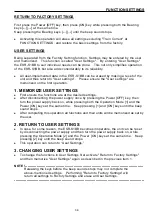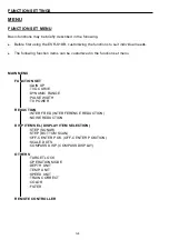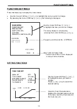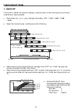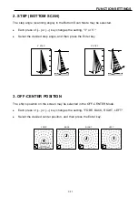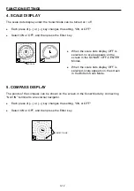
2-12
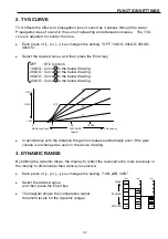
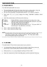
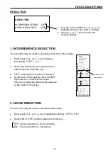
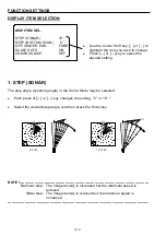
32.5
MA RK E R
CU RS OR
R AN GE
BE AR I NG
SE CT O R
TI LT
30.5
SONAR OPERATION
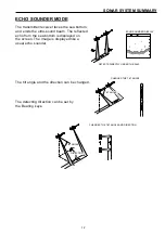
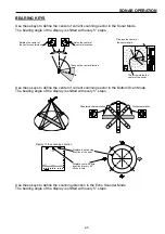
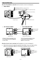
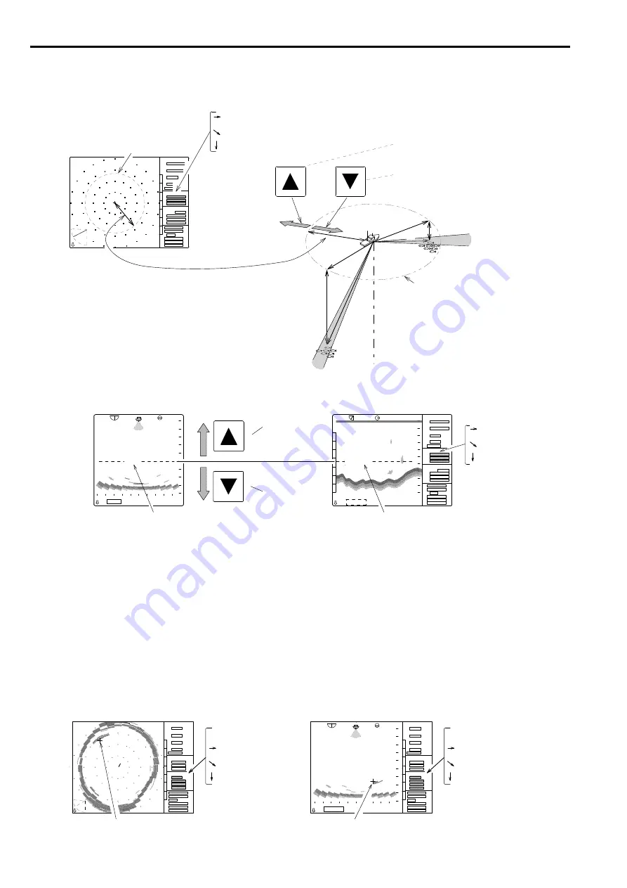
When the Ring Marker is selected
(the Cross Cursor is in red or not displayed,)
SONAR MODE
:HORIZONTAL DISTANCE (“a” in the below drawing)
:SLANT DISTANCE (“b” in the below drawing)
:DEPTH (“c” in the below drawing)
Changes this range.
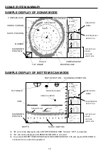
BOTTOM SCAN MODE
ECHO SOUNDER MODE
:HORIZONTAL DISTANCE
:SLANT DISTANCE
:DEPTH
MARKER & DEPTH MARKER & SLANT DISTANCE
In Bottom Scan Mode Marker data
is not presented and VRM appears
on the screen.
In Echo Sounder Mode Marker data
is presented and Slant distance
appears on the screen.
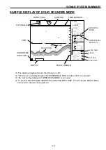
When the Cross Cursor is selected
(the Ring Marker is in red or not displayed,)
Set the Cross Cursor on a target by using the Cursor Shift [
↑
][
↓
][
←
][
→
] keys, and the
depth and horizontal/slant distance to the target are displayed in the Cursor box.
SONAR MODE
BOTTOM SCAN MODE
:BEARING :BEARING
:HORIZONTAL DISTANCE :HORIZONTAL DISTANCE
:SLANT DISTANCE :SLANT DISTANCE
:DEPTH :DEPTH
CROSS CURSOR CROSS CURSOR
+
RANGE
BEARING
SECTOR
TILT
MARKER
CURSOR
RANGE
BEARING
SECTOR
TILT
MARKER
CURSOR
32. 5
レンジ
旋回中心
セクター
俯角
マーカー
十字カーソル
c b
a
b
a
c
MARKER
This key lengthens the distance.
This key shortens the distance.
MARKER DISTANCE
MARKER DOWN
MARKER UP
Summary of Contents for ESR-S1BB
Page 1: ......
Page 56: ...4 3 INSTALLATION DIMENSIONS TRANSDUCER UNIT Unit mm OPERATION UNIT...
Page 58: ...4 5 INSTALLATION MOUNTING SOUNDOME INTO TD CASE...
Page 73: ......

