Kodak X-OMAT 7000 User Manual Download Page 29

Quick Reference Operating Instructions

7E6174 – 16FEB01

2– 9

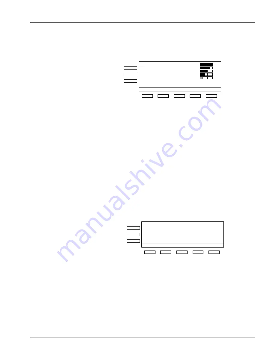
The Cassette will be pulled into the Multiloader and the orange status light will 
illuminate. The following will be displayed.

This indicates that a Cassette is inside the Multiloader and an unload/load operation 
cycle is in progress.

After unloading an exposed film and loading unexposed film, the Cassette will be 
returned. When the Cassette is removed the green status light will illuminate. The 
orange light will remain illuminated until the film exits the Multiloader.

The display will return to the main menu. The Multiloader is ready for the next 
operation.

If the green and orange status lights are illuminated, a film is still inside the 
Multiloader, but the system is ready to accept the next Cassette.

If the red status light flashes and the audible alarm sounds, remove the Cassette and 
press CLEAR to cancel the message on the Display Panel.

The warning message must be cancelled by pressing the soft switch marked CLEAR
after the Cassette has been removed.


PROC

SERIAL

LOAD

UNLOAD

FUNC

*

M A G. 1:

M A G. 2:

M A G. 3:

M A G. 4:

M A G. 5:

M A G. 6:

M A G. 7:

8 x 10 in

35 x 43 cm

35 x 43 cm

18 x 24 cm

24 x 30 cm

24 x 30 cm

18 x 24 cm

V

X

X

X

X

M

M

#2

?

EMPTY

ORANGE

GREEN

RED

ON

Soft Switches

Status Lights

H186_8501AC

H186_8504AC

RETURN

CODE

"BEEP"

Flashing

ON

RED

GREEN

ORANGE

CLEAR

CASSETTE NOT LOADED

Summary of Contents for X-OMAT 7000

Page 1: ...Eastman Kodak Company 2001 MiscellaneousPUB Production KodakServiceSupport Publication No 7E6174 16FEB01 User Guide for the KODAK X OMAT Multiloader 7000 H186_1000AC...

Page 2: ...Special Messages 5 Typeface Conventions 5 Introduction 1 1 Overview 1 1 Specifications 1 2 Radio Interference Suppression 1 4 Declaration of Conformity 1 4 Safety Standards 1 4 Environmental 1 4 Warn...

Page 3: ...the Start Up Option 5 25 Selecting the Display Units for Temperature and Transport Speed 5 28 Selecting a Stand By Mode 5 30 Selecting Sleep Mode Options 5 33 Procedure for Turning On and Off the Roll...

Page 4: ...4 16FEB01 7E6700...

Page 5: ...t Important notes highlight critical policy information that affects how you use this manual and this product Caution Cautions point out procedures that you must follow precisely to avoid damage to th...

Page 6: ...6 16FEB01 7E6174...

Page 7: ...osed film is fed into the KODAK X OMAT 3000 RA Integrated Processor Processor in the Multiloader which is capable of operating at 3 different user selectable cycles for either K RA Rapid or Standard c...

Page 8: ...rd 80 seconds 103 seconds 137 seconds Recommended Temperature K RA Rapid Standard 35 5 C 96 F 37 2 C 99 F 34 4 C 94 F Capacity 80 to 200 Cassettes hour Dimensions Width Height Depth Weight 820 mm 32 3...

Page 9: ...loper and Replenisher KODAK X OMAT RA 30 Fixer and Replenisher The unit is provided with separate drain valves for fixer and developer KODAK AG D 70327 Stuttgart Made in Germany SERVICE CODE SERIAL NU...

Page 10: ...Communications Le present appareil numerique n emet pas de bruits radioelectriques depassent les limites applicables aux appareils numeriques de las class A prescrites dans le Reglement sur le broulla...

Page 11: ...ng from the use of this information even if loss or damage is caused by Kodak s negligence or other fault Warning To avoid hazardous conditions keep floors and floor coverings around your Multiloader...

Page 12: ...X OMAT 3000 RA Integrated Processor as described in the Clean up and Maintenance section of this User Guide Always disconnect the Multiloader main power either the mains plug grasp the mains plug only...

Page 13: ...he Multiloader mains plug to a grounded outlet After installation from Kodak Service the mains plug must always be easily accessible The Heater Plenum is hot Use caution to avoid burns Before placing...

Page 14: ...of the patient and the device simultaneously by the caregiver is not allowed 3 No direct electrical connection is allowed between the device and the Patient Contact Equipment 4 According to European E...

Page 15: ...Operation of this equipment in a residential area is likely to cause interference in which case the user at the user s own expense will be required to take whatever steps may be required to correct th...

Page 16: ...is a mechanical hazard if the Safety Interlock System is bridged from the qualified service personnel during maintenance or repairs Warning The symbol below the RS232 connector indicates For the use o...

Page 17: ...Introduction 7E6174 16FEB01 1 11 Warning The Hot Surface symbol indicates this area is hot H186_1110GC...

Page 18: ...ust 24 hours a day 7 days a week Failure to follow this requirement will cause damage to the machine which will not be covered by any warranty How to Obtain Service Should the equipment require servic...

Page 19: ...this equipment even if loss or damage is caused by the negligence or other fault of Kodak Such damages for which Kodak will not be responsible include but are not limited to loss of revenue or profit...

Page 20: ...Introduction 1 14 16FEB01 7E6174...

Page 21: ...0 position before performing any of the following procedures Only Kodak trained personnel can perform the following procedures Wear rubber gloves safety glasses and protective clothing when doing any...

Page 22: ...rence Operating Instructions 2 2 16FEB01 7E6174 Warning Dangerous Voltage 1 Move the Circuit Breakers Loader and Processor on the back of the Multiloader to the 0 position Processor Loader ON OFF ON H...

Page 23: ...cessor until it locks in place and remove the Wet Section Cover 4 Check that the Racks and Crossovers are in their correct positions 5 Remove the Wash Reservoir H186_1086GC H186_1086GCB Front Panel Pr...

Page 24: ...der 7 Check that the 2 Crossover Troughs are on the bottom of the Developer Fixer and Fixer Wash Crossovers 8 Check that the developer and fixer solutions are near the overflow levels of each tank 9 I...

Page 25: ...11 when doing Step 13 13 Gently push in the Processor 14 Check that the Magazine Door and the Top Cover are closed and both Captive Screws are tight 15 Turn on the water Note The temperature of the in...

Page 26: ...rs on the back of the Multiloader to the 1 position 17 Press the Switch on the side of the Multiloader to the 1 position Note The Fan is running when the mains plug is connected or the wall mounted ma...

Page 27: ...reen status light will be illuminated The Multiloader is ready for use Note You can also program the Processor to turn on automatically by setting the automatic on off timers See Automatic On and Off...

Page 28: ...ssette sizes that are available Warning Do not place hands in the Cassette Entrance Release the Cassette as soon as it is pulled into the Multiloader 2 Insert the Cassette with the Latch side up and t...

Page 29: ...Multiloader is ready for the next operation If the green and orange status lights are illuminated a film is still inside the Multiloader but the system is ready to accept the next Cassette If the red...

Page 30: ...e red status light is constantly illuminated and the audible alarm sounds follow the instructions on the display and see Error Messages on page 6 10 For other functions see Special Functions on page 3...

Page 31: ...do the following to avoid condensation a Gently pull out the Processor until it locks into place b Remove the Wet Section Cover see Page 2 3 Note You can program the Multiloader to turn off automatica...

Page 32: ...Quick Reference Operating Instructions 2 12 16FEB01 7E6174...

Page 33: ...ect size film The Cassette is opened and the exposed film is removed and transported via the Conveyor to the Film Chute and Processor Interface The Interface feeds the film to the Processor The Multil...

Page 34: ...er can accept a Cassette Red Flashing CAUTION observe messages on the Display Panel Red On Malfunction indication observe messages on the Display Panel and follow the instructions Cassette Type Descri...

Page 35: ...m 24 x 30 cm 18 x 24 cm V X X X X M M 2 EMPTY ORANGE GREEN RED ON Soft Switches flashing nearly empty H186_8500AC H186_1088AC DESCRIPTION Soft Switch Description Unknown Magazine Position Film Size Ma...

Page 36: ...nel indicates the Magazine level without size application type and film quantity When a new Magazine is inserted or the same Magazine is inserted again the display shows a for the film quantity until...

Page 37: ...Important Do not carry the Magazine by the Handle the films may fall out if the Magazine is not closed completely 3 Lift the Magazine slightly and pull it straight out of the Drawer 4 Push the Magazi...

Page 38: ...e Magazine 7 Open a new Film Pack 8 Remove the films and fan them carefully 9 Remove the old films from the Magazine 10 Push the new films all the way into the Magazine Note Single emulsion films must...

Page 39: ...azine Drawer 14 Insert the Magazine into the Drawer 15 Check that the Magazine fits beyond the Black Rollers 16 Release the 2 Drawer Locks and push the Magazine Drawer gently back into the Multiloader...

Page 40: ...e Cassette display film usage statistics and change the display language Special Functions are displayed on the bottom line of the display Press the Soft Switch below the function to select the functi...

Page 41: ...ilm from a Cassette and not reload the film 1 Start at the Ready Status on the Display Panel 2 Press Unload The following is displayed 3 Insert a Cassette The Cassette is returned either with the Latc...

Page 42: ...re is no Magazine level free the following screen is displayed 2 Remove the Magazine The next Magazine inserted is identified as Serial Unloading Magazine If there is at least one magazine level free...

Page 43: ...r not is unloaded and Serial Unloading started During the unload cycle a count of the films removed from the Magazine is displayed When the Magazine is empty the Cassette is returned empty and unlatch...

Page 44: ...n menu then the emergency Cassette can be inserted Note Set the dryer temperature back to the normal value after Serial Unloading has finished and before proceeding with other functions Function Use F...

Page 45: ...Type 2 must be coded by your Kodak Service Representative or a Kodak trained key operator The Multiloader then automatically recognizes the special Cassette and loads it with the special film without...

Page 46: ...y the other sizes 5 Press TOTAL to display the number of films used last year and this year 6 Press CLEAR to return to the main menu Languages Use LANG to set the display language options A maximum of...

Page 47: ...ess FUNC 2 Press LANG 3 Press the desired language Soft Switch After the selection the display returns to the main menu 4 Press CLEAR to cancel your selection H186_8513AC ESPA DEUT CHANGE LANGUAGE ENG...

Page 48: ...Overview 3 16 16FEB01 7E6174...

Page 49: ...Processor Main Menus 2 Press MORE to display the second menu The GO TO SETUP selection requires an access code and is for Kodak trained Key Operators and Kodak Service Representatives o o PROCESSOR RE...

Page 50: ...the film standard STD rapid RAPID K RA Standard and rapid are selected as follows 1 At the Processor Main Menu press SELECT CYCLE 2 Press the appropriate key for the required cycle DRYER Increase the...

Page 51: ...Films hour K RA USA 48 58 RA Films and RA Chemicals 270 K RA Outside USA 64 77 RA Films and RA Chemicals 201 Rapid 64 77 KODAK Films and KODAK X OMAT Chemicals 148 Standard 86 105 KODAK Films and KOD...

Page 52: ...lenoids remain off while the Processor is in the sleep mode While the Processor is in the sleep mode you cannot feed films or access any of the Processor setup screens 1 At the Processor Main Menu pre...

Page 53: ...ve not programmed the Automatic On and Off Timers the display will show the message Processor in Sleep Mode Exiting Sleep Mode There are 2 ways to exit the sleep mode If you have programmed the Automa...

Page 54: ...ll be displayed for the fixer solution Note The setpoint temperature for the fixer solution is a minimum only the temperature may rise above this set point To return to the Processor Main Menu press D...

Page 55: ...edures Wear rubber gloves safety glasses and protective clothing when doing the weekly maintenance Report any change in the operating condition of the Processor to your Kodak Service Representative Re...

Page 56: ...ers or Rollers using abrasive materials or alcohol To prevent fixer or developer contamination when removing the Fixer or Developer Rack place the Splash Guard between the Developer and Fixer Tanks Us...

Page 57: ...sconnect the main power either the mains plug grasp the mains plug only or move the wall mounted main switch to the 0 position from the Multiloader 2 Release both Latches Gently pull out the Processor...

Page 58: ...al deposits from the processing section 7 Check all Rollers on the Crossovers and Wash Rotate rotate freely the squareness of the Crossovers and the Wash Rack the Crossover Troughs are not broken or c...

Page 59: ...n Caution Before moving the Processor any further move your hands away from the Stop Bracket Place both hands into the openings of the left and right Latches on the Front Cover of the Processor to avo...

Page 60: ...Operating Instructions 4 12 16FEB01 7E6174...

Page 61: ...t is also possible to code each size from the list below as a Type 2 film 1 Remove the 6 Screws and the Magazine Cover Film General Radiography Mammography CRT Dental 18 x 43 cm 20 x 40 cm 24 x 24 cm...

Page 62: ...zine cannot be closed 2 Place the Stops in the Recesses corresponding to the film size The film sizes are marked in the recesses If you do not use all the Stops for the rear place the extra Stops to t...

Page 63: ...0 0 0 1 0 1 0 18 x 43 cm 1 0 0 1 0 0 1 0 0 1 1 0 24 x 30 cm 0 1 0 1 0 0 0 1 0 1 1 0 35 x 43 cm 0 0 1 1 0 0 0 0 1 1 1 0 30 x 40 cm 0 1 1 1 0 0 0 1 1 1 1 0 15 x 30 cm 0 0 0 0 1 0 0 0 0 0 0 1 8 x 10 in C...

Page 64: ...en the films and the Stops in the Magazine There must be no more than 4 mm 0 157 in clearance between the films and the Stops If the play is too great remove the films and check the setting of the Sto...

Page 65: ...can be ordered from Kodak Part No 9194551 The KODAK MIN R 2 Cassette and KODAK X OMATIC Video Film Holder Cassette Reflective Stickers are very easy to install as the correct position is marked by a r...

Page 66: ...6174 C3 Cassette MIN R 2 Cassette Note For TYPE 2 coding install 2 Reflective Stickers on the Mammography Cassette H186_1042AC H186_1042ACA TEMPLATE 9194501 REFLECTIVE STICKER 8 X 15 mm H186_1043AC RE...

Page 67: ...X OMATIC Video Film Holder Note For KODAK X OMATIC Video Film Holders install the Reflective Stickers either at the right or left side C1 or C3 of the Film Holder H186_1044AC H186_1044ACA 8 X 15 mm C1...

Page 68: ...re are two groups of failures which can occur in the Multiloader Failures that can only be solved by your Kodak Service Representative Failures which can be corrected by the operator or by the Multilo...

Page 69: ...The Multiloader brings all Motors to the home position and checks their functions If successful the green Status Light illuminates and you can start working again If this automatic test was not succes...

Page 70: ...174 Multiloader Key Operator Instructions PR IN MS CA SY MA RETURN CLEAR XX XX XX XX XX H186_8602AC AUTOMATIC RESET OF THE MULTILOADER If successful the unit is ready for operation again If not succes...

Page 71: ...m of the wrong size detection might be solved although there is a failure in the size direction Inform your Kodak Service Representative of this failure The magazine detection is correct are the Casse...

Page 72: ...ted below select Processor cycles except K RA change dryer temperature display fixer temperature place the Processor in the sleep mode display the time and the date 1 On the Processor Main Menu press...

Page 73: ...ons 7E6174 16FEB01 5 13 2 Press MORE Screen 2 of the Processor Main Menu is displayed 3 Press GO TO SETUP o o PROCESSOR READY DISPLAY GO TO DONE 127 F DRYER TEMP FIX TMP SETUP RETURN 95 F DEV TEMP STD...

Page 74: ...Circuit Breakers Loader and Processor on the back of the Multiloader to the 0 position Always disconnect the main power either the mains plug grasp the mains plug only or move the wall mounted main sw...

Page 75: ...B01 5 15 1 Open the Fixer and Developer Drain Valves 2 Drain the chemicals into provided containers and perform disposal of the chemicals according to your local regulations H186_1076GC H186_1076GCA D...

Page 76: ...of the Multiloader to the 0 position Always disconnect the main power either the mains plug grasp the mains plug only or move the wall mounted main switch to the 0 position from the Multiloader 1 Chec...

Page 77: ...mistry is needed for the operating cycle that you selected Warning Wear rubber gloves safety glasses and protective clothing when mixing chemistry 3 Following all directions provided with the solution...

Page 78: ...rom the Replenishment Tanks until the Level Sensors detect that the Processor tanks are full Warning Move the Circuit Breakers Loader and Processor on the back of the Multiloader to the 0 position Alw...

Page 79: ...ing See Step 9 on 4 11 4 Connect the Multiloader main power either the mains plug grasp the mains plug only or move the wall mounted main switch to the 1 position 5 Move the Circuit Breakers Loader an...

Page 80: ...ess GO TO SETUP 10 Enter the 4 digit access code 11 Press MORE H186_8522AC DATE TIME STD 95 0 F DEV TEMP RETURN SETUP FIX TEMP 127 4 F DRYER TEMP DONE GO TO DISPLAY PROCESSOR READY H186_8523AC 4 2 REQ...

Page 81: ...y 4 minutes The Developer and Fixer Tanks will not fill if the Processor is not pushed into the Multiloader The Developer and Fixer Tanks require approximately 10 minutes to fill with solution When th...

Page 82: ...to the drive side of the Developer Tank in the Processor 17 After the Replenishment Pumps stop operating check that a the levels of both the Developer and the Fixer Solutions in the Tanks are at the...

Page 83: ...e added automatically every 5 minutes achieving a minimum replenishment of 780 ml hr during Processor operation and when the equivalent film area of 35 x 43 has been processed Tank Fill Mode Select th...

Page 84: ...Instructions 5 24 16FEB01 7E6174 2 Enter the 4 digit access code 3 Press MORE 4 Press OPTIONS H186_8523AC 4 2 REQUEST CANCEL 3 1 DRYER DRYER CYCLE DONE RETURN MORE H186_8524AC H186_8525AC OPTIONS RETU...

Page 85: ...ONE RETURN several times to store the entry and return to the Processor Main Menu Selecting the Start Up Option The Daily Start Up option temporarily disables the Automatic Start Up feature of Sleep M...

Page 86: ...O TO SETUP 2 Enter the 4 digit access code 3 Press MORE H186_8522AC DATE TIME STD 95 0 F DEV TEMP RETURN SETUP FIX TEMP 127 4 F DRYER TEMP DONE GO TO DISPLAY PROCESSOR READY H186_8523AC 4 2 REQUEST CA...

Page 87: ...rn on or turn off the Automatic Start Up feature 7 Press ON or OFF 8 Press DONE RETURN several times to return to the Processor Main Menu H186_8526AC MORE DAILY STARTUP RETURN UNITS MODE DONE DISPLAY...

Page 88: ...rature units and English in min or metric cm min units for transport speed Default Setting English F and in min 1 Press GO TO SETUP 2 Enter the 4 digit access code 3 Press MORE H186_8522AC DATE TIME S...

Page 89: ...ss ENGLISH for F and in min or METRIC for C and cm min 7 Press DONE RETURN several times to return to the Processor Main Menu H186_8525AC OPTIONS RETURN DONE SETUP H186_8531AC MORE DAILY STARTUP RETUR...

Page 90: ...ollers are wet In the continuous mode the Transport System operates continuously at a reduced speed to ensure that the Rollers are wet In both modes the Dryer Blower and Heater turn on as required to...

Page 91: ...ions 7E6174 16FEB01 5 31 3 Press MORE 4 Press OPTIONS 5 Press MORE DRYER DRYER CYCLE DONE RETURN MORE H186_8524AC H186_8525AC OPTIONS RETURN DONE SETUP H186_8533AC MORE DAILY STARTUP RETURN UNITS MODE...

Page 92: ...ANDBY MODE 7 Press INTER MODE or CONT MODE 8 Press DONE RETURN several times to return to the Processor Main Menu H186_8534AC MORE ROLLER JOG RETURN DOWN MODE DONE COOL STANDBY MODE MODE INTER DONE RE...

Page 93: ...the Processor in Sleep Mode The Cool Down option reduces the condensation in the Processor Cabinet When selected the dryer blower operates for 3 hours to exhaust the moist warm air from the Processor...

Page 94: ...or Instructions 5 34 16FEB01 7E6174 3 Press MORE 4 Press OPTIONS 5 Press MORE DRYER DRYER CYCLE DONE RETURN MORE H186_8524AC H186_8525AC OPTIONS RETURN DONE SETUP DRYER DRYER CYCLE DONE RETURN MORE H1...

Page 95: ...on 8 Press DONE RETURN several times to return to the Processor Main Menu Turning On or Off the Cool Down Option 1 Press GO TO SETUP H186_8537AC MORE ROLLER JOG RETURN DOWN MODE DONE COOL STANDBY H186...

Page 96: ...Instructions 5 36 16FEB01 7E6174 2 Enter the 4 digit access code 3 Press MORE 4 Press OPTIONS H186_8523AC 4 2 REQUEST CANCEL 3 1 DRYER DRYER CYCLE DONE RETURN MORE H186_8524AC H186_8525AC OPTIONS RETU...

Page 97: ...e the Cool Down option or OFF to disable the Cool Down option 8 Press DONE RETURN several times to return to the Processor Main Menu H186_8533AC MORE DAILY STARTUP RETURN UNITS MODE DONE DISPLAY REPLE...

Page 98: ...portant You must use RA chemicals to process films when using the K RA cycle 1 Press GO TO SETUP 2 Enter the 4 digit access code 3 Press CYCLE H186_8522AC DATE TIME STD 95 0 F DEV TEMP RETURN SETUP FI...

Page 99: ...4 16FEB01 5 39 4 Select the required cycle 5 Press DONE RETURN to store the entry and to return to the Processor Main Menu See Cycle Information for the Processor on Page 4 3 H186_8541AC K RA CYCLE ST...

Page 100: ...default cycle options US default setting Europe Japan 1 Press GO TO SETUP 2 Enter the 4 digit access code 3 Press MORE H186_8522AC DATE TIME STD 95 0 F DEV TEMP RETURN SETUP FIX TEMP 127 4 F DRYER TEM...

Page 101: ...174 16FEB01 5 41 4 Press OPTIONS 5 Press MORE 6 Press MORE H186_8525AC OPTIONS RETURN DONE SETUP H186_8533AC MORE DAILY STARTUP RETURN UNITS MODE DONE DISPLAY REPLEN H186_8542AC MORE ROLLER JOG RETURN...

Page 102: ...EB01 7E6174 7 Press CYCLE DEFAULT 8 Press the appropriate key 9 Press DONE RETURN several times to store the entry and to return to the Processor Main Menu H186_8543AC RETURN DEFAULT DONE CYCLE H186_8...

Page 103: ...future use Setpoints that were preset at the factory can always be restored by pressing the DEFAULT SETTING in Step 9 on 5 45 1 Press GO TO SETUP 2 Enter the 4 digit access code 3 Press MORE H186_8522...

Page 104: ...74 4 Press SETUP 5 Press PROCESS 6 Press the key for the current film processing cycle H186_8545AC OPTIONS RETURN DONE SETUP H186_8546AC PUMP CALIB CLOCK RETURN STARTUP DONE AUTO PROCESS H186_8541AC K...

Page 105: ...ture 9 To change the temperature setpoint press the a to increase b to decrease c DEFAULT SETTING to return to the factory setpoint d CANCEL REQUEST to return to the last value set 10 Do Steps 8 and 9...

Page 106: ...s 5 46 16FEB01 7E6174 11 Press DONE RETURN several times to store the entry and to return to the Processor Main Menu Note The temperature setpoint for the fixer is a minimum only the temperature may r...

Page 107: ...r the volume for the Developer and Fixer Replenishment on the keypad for high film usage The Microprocessor automatically calculates the replenishment volumes for low and medium film usage In the Floo...

Page 108: ...Instructions 5 48 16FEB01 7E6174 2 Enter the 4 digit access code 3 Press MORE 4 Press SETUP H186_8523AC 4 2 REQUEST CANCEL 3 1 DRYER DRYER CYCLE DONE RETURN MORE H186_8524AC H186_8545AC OPTIONS RETUR...

Page 109: ...9 5 Press PROCESS 6 Press the current operating cycle 7 Press REPLEN VOLUME H186_8546AC PUMP CALIB CLOCK RETURN STARTUP DONE AUTO PROCESS H186_8541AC K RA CYCLE STD CYCLE RETURN CYCLE DONE RAPID H186_...

Page 110: ...ONE RETURN several times to store the entry and to return to the Processor Main Menu 11 Do Steps 8 10 for the other solution Verifying the Replenishment Rates Warning Gloves and protective eye wear mu...

Page 111: ...the Replenishment Pumps to turn on and deliver the preset volume of replenishment solution 6 Compare the volume of replenishment solution in the Graduated Cylinder of the replenishment volume you set...

Page 112: ...value is stored for that cycle To change the transport speed 1 Press GO TO SETUP 2 Enter the 4 digit access code 3 Press MORE H186_8522AC DATE TIME STD 95 0 F DEV TEMP RETURN SETUP FIX TEMP 127 4 F DR...

Page 113: ...FEB01 5 53 4 Press SETUP 5 Press PROCESS 6 Select the current operating cycle H186_8545AC OPTIONS RETURN DONE SETUP H186_8546AC PUMP CALIB CLOCK RETURN STARTUP DONE AUTO PROCESS H186_8541AC K RA CYCLE...

Page 114: ...times to store the entry and to return to the Processor Main Menu Setting the Time and Date Set the clock of the Processor to take advantage of the following features Auto Start Up and Shut Down Time...

Page 115: ...O TO SETUP 2 Enter the 4 digit access code 3 Press MORE H186_8522AC DATE TIME STD 95 0 F DEV TEMP RETURN SETUP FIX TEMP 127 4 F DRYER TEMP DONE GO TO DISPLAY PROCESSOR READY H186_8523AC 4 2 REQUEST CA...

Page 116: ...16FEB01 7E6174 4 Press SETUP 5 Press CLOCK 6 Press TIME FORMAT H186_8545AC OPTIONS RETURN DONE SETUP H186_8553AC PUMP CALIB CLOCK RETURN STARTUP DONE AUTO PROCESS H186_8554AC TIME DATE DATE FORMAT SE...

Page 117: ...ptions 9 Press DATE FORMAT 10 Select the desired FORMAT 11 Press DONE RETURN once to return to the set time and set date options H186_8555AC FORMAT FORMAT 24 HOUR RETURN DONE 12 HOUR H186_8556AC TIME...

Page 118: ...s to set the time in hours and minutes 14 Press DONE RETURN once to return to the set date option 15 Press SET DATE H186_8558AC TIME DATE DATE FORMAT SET RETURN FORMAT DONE TIME SET H186_8559AC HOUR H...

Page 119: ...DATE 17 Use the up and down arrow keys to set the date 18 Press DONE RETURN once to return to the set year option 19 Press SET YEAR H186_8561AC DATE YEAR SET RETURN DONE SET H186_8562AC MONTH MONTH DA...

Page 120: ...y to accept films by the time you arrive at work in the morning you could set Timer 1 to turn on the Processor at 6 00 a m If you operate during 2 distinct shifts and there is a large lapse in time be...

Page 121: ...completed the procedure for setting the time and date starting on Page 5 54 1 Press GO TO SETUP 2 Enter the 4 digit access code 3 Press MORE H186_8522AC DATE TIME STD 95 0 F DEV TEMP RETURN SETUP FIX...

Page 122: ...ions 5 62 16FEB01 7E6174 4 Press SETUP 5 Press AUTO STARTUP 6 Press ON H186_8545AC OPTIONS RETURN DONE SETUP H186_8565AC PUMP CALIB CLOCK RETURN STARTUP DONE AUTO PROCESS H186_8566AC ON RETURN OFF AUT...

Page 123: ...me 8 Press TIMER1 CONTROL 9 Press ON TIME H186_8567AC SET TIMERS ON RETURN OFF AUTO STARTUP IS ON DONE H186_8568AC TIMER1 CONTROL TIMER2 CONTROL COPY PREV NEXT DAY RETURN PRESS BUTTON TO SET UP FOR MO...

Page 124: ...ting the Off Time Note Any time the screen shown below appears on the Display Panel you can press OFF to erase the last programmed on and off times for Timer 1 and Timer 2 12 Press OFF TIME H186_8570A...

Page 125: ...Timer 2 CONTROL 2 Repeat Steps 9 through 14 starting on Page 5 63 to set the On and Off Times for Timer 2 Then set the On and Off Timers for the remaining days of the week H186_8573AC MINUTE HOUR HOUR...

Page 126: ...ot want to repeat Monday s on and off times for the other days of the week follow Steps 1 10 on Page 5 68 Copying On and Off Timer Settings 1 Press NEXT DAY 2 Press COPY PREV 3 Repeat the entire proce...

Page 127: ...following steps 1 Press NEXT DAY to advance the display to show Tuesday 2 Press Timer 1 CONTROL 3 Press ON to enable Timer 1 H186_8576AC TIMER1 CONTROL TIMER2 CONTROL COPY PREV NEXT DAY RETURN PRESS...

Page 128: ...ocessor should turn on 6 Press DONE RETURN until you return to the menu options shown below Then press OFF TIME H186_8580AC ON TIME OFF TIME ON OFF RETURN SET UP TIMER1 FOR TUESDAY DONE H186_8581AC MI...

Page 129: ...ons displayed below Then press Timer 2 CONTROL 9 Repeat Steps 4 through 8 to set the on and off time settings for Timer 2 10 Repeat the entire process to set the Automatic Timers for the remaining day...

Page 130: ...ing a set period of time then use the Display Panel to enter the measurement into the Microprocessor The Microprocessor computes the rate of solution flow through the Pump then adjusts the period of t...

Page 131: ...ctions 7E6174 16FEB01 5 71 3 Press MORE 4 Press SETUP 5 Press PUMP CALIB DRYER DRYER CYCLE DONE RETURN MORE H186_8524AC H186_8545AC OPTIONS RETURN DONE SETUP H186_8585AC PUMP CALIB CLOCK RETURN STARTU...

Page 132: ...h large amounts of water If irritation persists check with a doctor Replenishment solutions are pumped quickly and may splash 7 Carefully pull out the Processor until it locks into place 8 Remove the...

Page 133: ...h 11 at least 2 more times 14 Determine the average volume of replenishment delivered 15 Install the replenishment hose into the Fixer or Developer Filter Mandrel 16 Carefully push the Processor back...

Page 134: ...DONE RETURN several times until you return to the Processor Main Menu 20 Repeat Steps 6 to 18 for the Developer or Fixer Replenishment 21 Press DONE RETURN several times until you return to the Proce...

Page 135: ...Problem Solving Warning Move the Circuit Breakers Loader and Processor on the back of the Multiloader to the 0 position Always disconnect the main power either the mains plug grasp the mains plug onl...

Page 136: ...7E6174 1 Release both Latches Gently pull out the Processor to avoid splashing Warning See Step 9 on 4 11 2 Gently push the Processor back into the Multiloader until the Latches click into position H...

Page 137: ...Tubes especially the Air Tube slot and Air Diffuser Use a Bottle Brush and rinse with water Check the settings for correct replenishment Check the external tubing of the replenishment system i e tubi...

Page 138: ...mperature Temperature must be between 4 C 40 F and 29 C 85 F If 10 x 10 cm films fail to transport reliably feed the sheets of films diagonally For DFF only Check that solution Level Probes are clean...

Page 139: ...s manually Warning Move the Circuit Breakers Loader and Processor on the back of the Multiloader to the 0 position Always disconnect the main power either the mains plug grasp the mains plug only or m...

Page 140: ...sette 4 Push the Centering Bars to the full width 5 Lift and remove the Cassette 6 Push the Top Cover slightly upwards to release both Cover Stays 7 Tighten both Captive Screws 1 4 turn clockwise 8 Pr...

Page 141: ...r on the back of the Multiloader to the 0 position Always disconnect the main power either the mains plug grasp the mains plug only or move the wall mounted main switch to the 0 position from the Mult...

Page 142: ...Troubleshooting and Error Messages 6 8 16FEB01 7E6174 H186_1000AC H186_1000ACH Screw Captive Screw Captive Door Magazine Top Cover...

Page 143: ...ease and push the 7 Magazines to the back of the Multiloader 6 Pull one of the 7 Magazines forward to remove the Magazine from the Multiloader 7 Close the Magazine Door 8 Push the Top Cover slightly u...

Page 144: ...as been set on installation as no film was loaded Please check correct magazine insertion The magazine is probably not positioned correctly Please insert correct cassette size SERIAL UNLOADING The Cas...

Page 145: ...le To close the Top Cover push the Top Cover slightly upwards to release both Cover Stays Tighten both Captive Screws 1 4 turn clockwise Cassette out transport failed Open cover to remove cassette Cas...

Page 146: ...Printed in U S A 7E6174_06 fm EASTMAN KODAK COMPANY Rochester NY 14650 Kodak Min R X Omatic and X Omat are trademarks of Eastman Kodak Company...

Reviews: