94
1.8.3.
Plan link
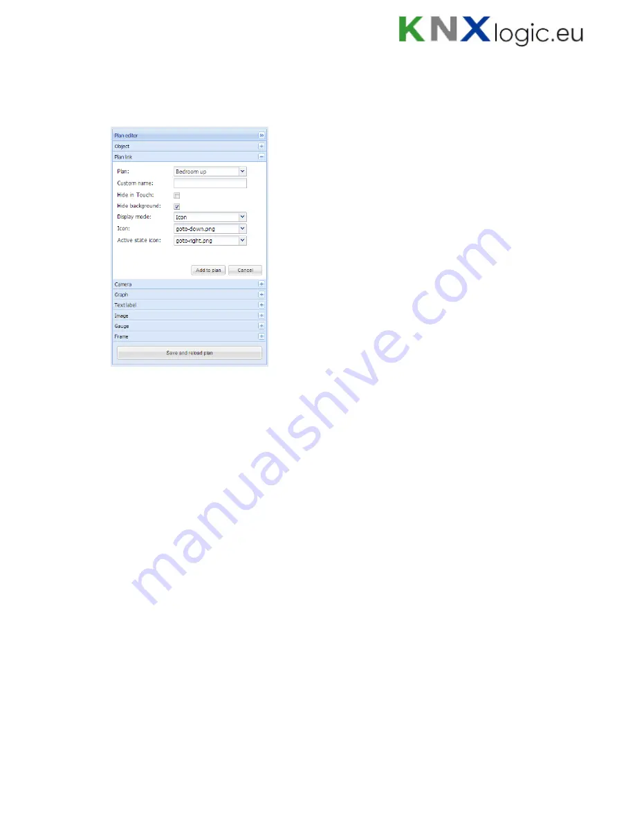
In order to make visualization more convenient, there are floor links integrated. You can add
icons or text on the map, which links to other floors.
Plan
– Linked plan name or link to Schedulers / Trends
Custom name
– name for the link
Hide background
– Hide icon background
Display mode [Icon; Value]
– either to show icon or its value
Icon
– Icon which will be showed in visualization (if chosen, no further parameters
are available)
Active state icon – active state icon if the link is to current plan (in case you have
several smaller plans on one visualization and want to display the current one)
Font size
– size of font
Text style
– text style – bold, italic, underscore
Custom font
– font name
Font color
– font color
Once the floor link parameters are defined, press
Add to plan
button and newly created object
will appear. You can move the object to the location it will be located. Note that while being in
editing mode, the object will not work. Press on
Save and reload plan
button so the objects starts
functioning.
1.8.4.
Camera
Logic Machine supports third party IP web camera integration into its visualization.
Summary of Contents for LogicMachine3 Re:actor
Page 10: ...10 Terminal connection schemes KNX TP...
Page 12: ...12 24V power supply...
Page 13: ...13 Analog inputs e g reed contact...
Page 14: ...14 Analog inputs 0 10V...
Page 15: ...15 Digital output...
Page 16: ...16 Resistive sensor input...
Page 17: ...17 Analog output...
Page 26: ...26 Make sure that bus status is Online press button in ETS...
Page 35: ...35 o Then minimize side bar by pressing on left arrow icon to make the map more visible...
Page 83: ...83 66 if err then 67 alert FTP upload failed s err 68 end...
Page 107: ...107...
Page 108: ...108 1 14 Help Documentation for scripting syntaxes is displayed in Help tab...
Page 126: ...126 Datapoints can be shown also in a way of table which can be later exported as CSV file...
Page 141: ...141...


