


Service manual LIMAX
120
Service manual version 1.00
page 73
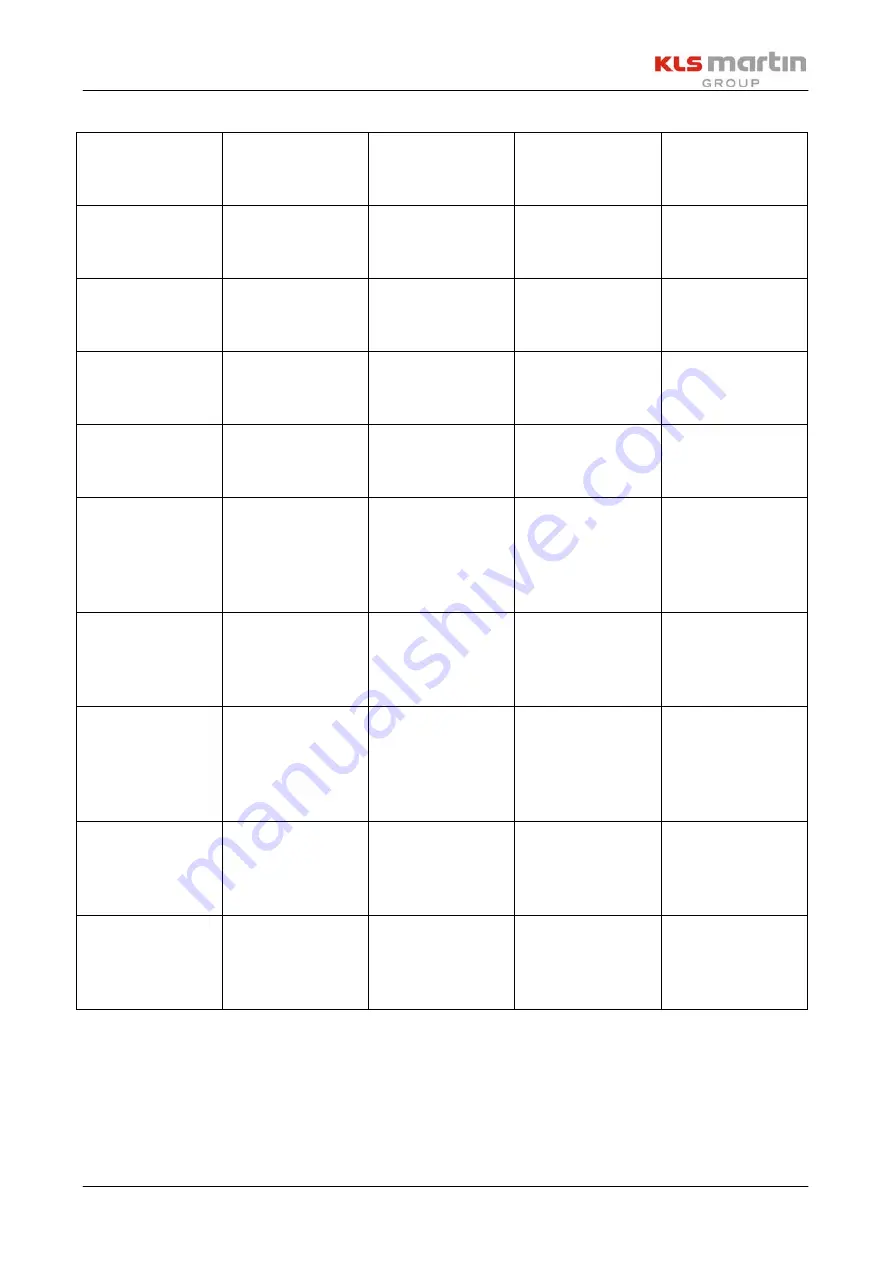
Status-Code
Error
description
First step done
by user
Second step
done by user
Service
operation done
by technician
1069
Warning: valid
service log
missing
-
-
Replace
controller PCB
1070
Warning: two
different service
logs found
-
-
Replace
controller PCB
1071
Warning: i2c
communication
error
-
-
Replace
controller PCB
1072 to 1080
Warning: SPI
communication
error
-
-
Replace
controller PCB
2002
Grave error:
LASER READY
without safety
system
registering
Press down
STANDBY
Call service
Replace
controller PCB
2003
Grave error:
Laser activated
without LASER
READY
Press down
STANDBY
Call service
Replace
controller PCB
2004
Grave error:
Laser activated
while LASER
READY status
changed
Press down
STANDBY
Call service
Replace
controller PCB
2005
Grave error:
LASER READY
while interlock
connector open
Press down
STANDBY
Call service
Replace
controller PCB or
power supply
unit
2006
Grave error:
Laser activated
while interlock
connector open
Press down
STANDBY
Call service
Replace
controller PCB or
power supply
unit


