background image

Operating manual 17.410+411   

Pos.:  20


Dateiname 

Firma  

Datum  

Rev  

BK-DH 700 x 1000 eng.doc 

BRUKS-KLÖCKNER 

27.02.09 

00 

Seite 52 von

 61


9.2 

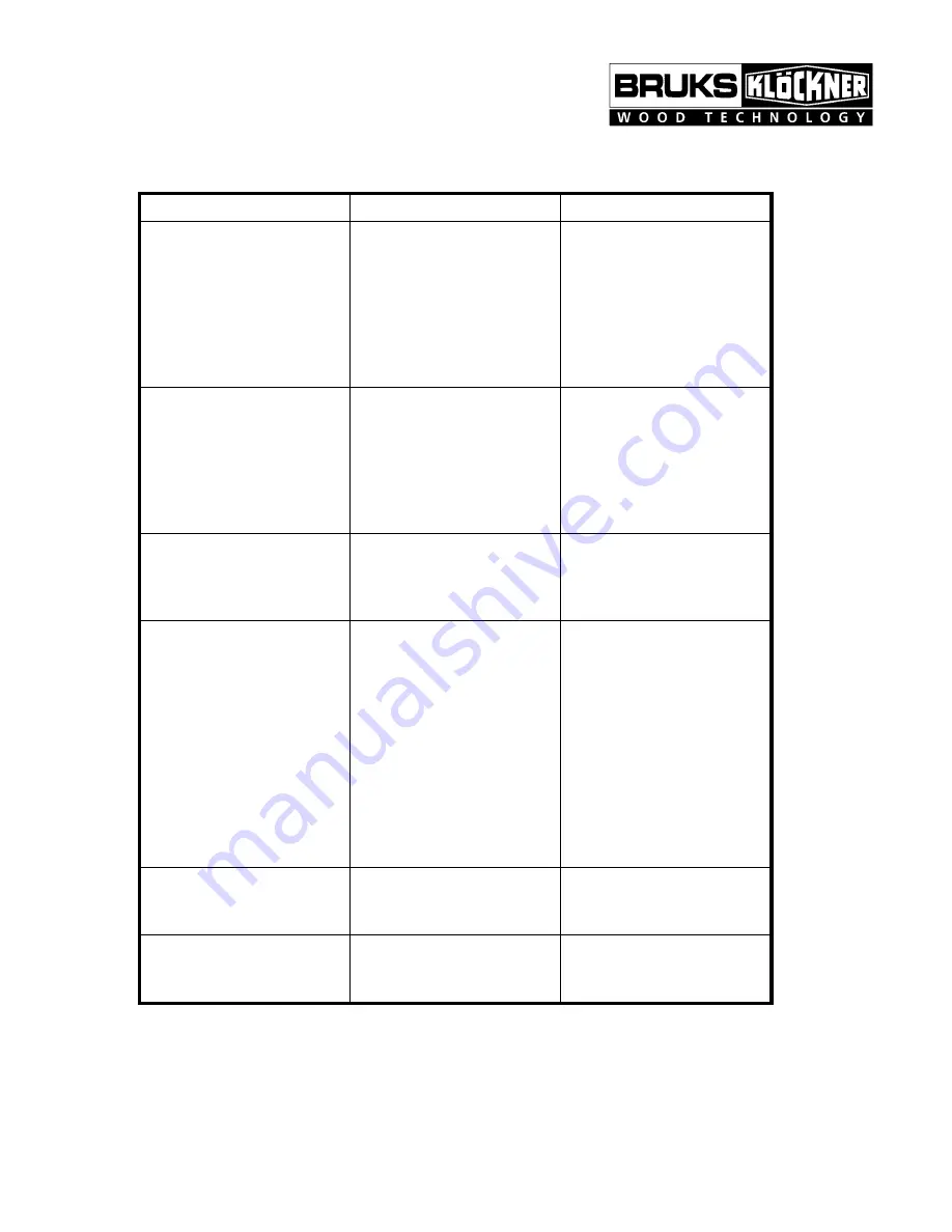
Problems with the machine 

 
problem 

possible cause 

suggested solution 

rotor slow down 

automatic feed control 
defective 
dull knives 
 
 
take away conveyor of 
inadequate capacity 

check controls and repair 
if necessary 
grind knives 

(see chap-

ter „inspection and 
maintenance works“)


increase capacity 
 

frequent activation of the 
load control 

dull knives 
load control defective 
 
main motor too small 
 
chipping volume too high 

regrind or change knives


check control and repair 
if necessary 
check and increase mo-
tor power 
reduce volume 

machine vibrates  

imbalance of rotor due to 
uneven ground knives 

grind all knives in one set 
to equal width 

(see chap-

ter „inspection and 
maintenance“)


unsatisfactory indeed 

teeth of feedrolls worn 
oil pressure (p3) too high 
or too low 
 
gas pressure (p1) wrong 
 
 
feedroll carrier lowers too 
slowly 

replace feedrolls 
adjust oil pressure (p3) 

(see chapter „inspec-
tion and maintenance“)

adjust gas pressure (p1) 

(see chapter „inspec-
tion and maintenance 
works“) 

adjust lowering speed 

(see chapter „installa-
tion“)


feedroll carrier stops too 
hard 

feedroll carrier drops too 
fast 

adjust lowering speed 

(see chapter „installa-
tion“)


gear motor cannot start 
lower feedrolls


feedrolls jammed with 
material between feedroll 
and troughside


remove material re-adjust 
trough side with adjusting 
screws


Summary of Contents for BK-DH 500 SERIES

Page 1: ...Operating manual 17 410 411 Pos 20 Dateiname Firma Datum Rev BK DH 700 x 1000 eng doc BRUKS KL CKNER 27 02 09 00 Seite 1 von 61 DRUM CHIPPER Type BK DH 500 x BK DH 700 x BK DH 850 x...

Page 2: ...3 1 2 Feedroll carrier pivot 11 3 1 3 Lower feedrolls and bearings 11 3 1 4 Upper feedrolls and bearings 11 3 1 5 Counter knife carrier 12 3 1 6 Rotor 12 3 1 7 Hood 12 3 1 8 Screen 12 3 1 9 Feedroll c...

Page 3: ...down for chipment 21 4 5 Scope of supply 22 5 INSTALLATION 23 5 1 General comments 23 5 2 Set up and preliminary alignment 24 5 3 Installation of hydraulic plant 24 5 4 Installation of lower feedroll...

Page 4: ...8 1 General comments 38 8 2 Maintenance and inspection list 39 8 3 Knives 41 8 3 1 Knife grinding 41 8 3 1 1 Grinding of knives 41 8 3 1 2 Grinding of counter knives 42 8 3 2 Knife setting 43 8 3 3 R...

Page 5: ...tor wear plates optional 49 8 11 Feedrolls 49 8 12 Screen 50 8 13 Lubrication 50 9 TROUBLE SHOOTING 51 9 1 Problems with the chip quality 51 9 2 Problems with the machine 52 9 3 Problems with the hydr...

Page 6: ...ation of the drum chipper and it is very important that the appropriate personnel is fully familiar with this man ual We strongly recommend the reading of this manual prior to installation start up or...

Page 7: ...different purpose or to produce a different product you are urged to discuss this with BRUKS KL CKNER GmbH 1 3 Copyright The copyright of this operation manual remains property of BRUKS KL CKNER GmbH...

Page 8: ...ly for the production of chips from wood Any other use is improper and no responsibility can be accepted by the manufacturer 2 4 The user is responsible to protect the machine from foreign metal or ro...

Page 9: ...rds for maintenance they must be re installed imme diately upon completion of the work 2 16 The hydraulic unit is equipped with an accumulator This may have to be inspected and approved by the local a...

Page 10: ...t must be secured with the holding pin 2 22 When working underneath the cradle it must be secured with the cradle support 2 23 When working on the rotor it must be secured with the holding pin 2 24 Wh...

Page 11: ...s The feedrolls with special tooth profile are running in heavy spherical roller bearings in flanged steel housings spigotted in the housing sidewalls Seals are lip type The teeth of the feedrolls are...

Page 12: ...andard knife mounting is by clamping plates with bolts tapered wedge type knife clamping is also available The rotor is provided with replaceable wearplates underneath the knives The rotor is mounted...

Page 13: ...n the power transmis sion connection is to be effected by means of a jaw clutch or bolt coupling The pul ley is fastened by means of cone clamping devices on the shaft The bearing is per formed by hea...

Page 14: ...in motors by an installed hydraulic motor When reaching the rated speed the main motors are hooked up into the electric net work with the result that high power withdrawal of the electric network is p...

Page 15: ...aulic cylinder Dur ing the work clearance stroke this ratchet engages into a toothed disc mounted onto the rotor shaft and turns it By repeating this process the rotor is turned until the re spective...

Page 16: ...a screen changing device The rear side of the chipper and the screen changing device are forming a unit To unlock the rear side of the chipper release the swivelling screw fittings Through the hydrau...

Page 17: ...ng operation The knives chip the material by cutting the length of the chip with the thickness re sulting from the knife angle and specific characteristics of the wood being chipped The chips are coll...

Page 18: ...tch off of the hydraulic system in free wheeling operation This clutch works wear resisting because of the hydro dynamic clamping piece lift off 3 2 6 Hydraulic functions Reducing the swing contact pr...

Page 19: ...for manual support of infeed Function continuously available by key operation touch control contact b During standstill for cleaning or repair works Unconditionally secure the swing with the swing sup...

Page 20: ...e lifting lugs as shown see drawing below 4 1 2 The drum chipper must be carefully handled to prevent damage caused by force or careless loading and unloading 4 1 3 During transportation the machine m...

Page 21: ...r ing If stored outside the chipper must sit on supports and not directly on the ground Machines and parts that are completely packed in boxes foil etc the packing must not be removed until installati...

Page 22: ...DH 700 x 1000 eng doc BRUKS KL CKNER 27 02 09 00 Seite 22 von 61 4 5 Scope of supply The contents of the shipment must be checked on arrival against the packing list Any discrepancies shortages or dam...

Page 23: ...ctions The user is advised to have this confirmed by signature of the appropriate personnel The drum chipper can be mounted on a concrete foundation or a solid steel structure The design of the suppor...

Page 24: ...e machine by means of the sup plied hoses See enclosed hydraulic diagram The plugs in the fittings of the ma chine and power pack must be removed The hoses are ready for installation the union must be...

Page 25: ...otors and hydraulic pump motor are connected electrically and run for a short time Check for rotation The top feedroll carrier is raised with feedroll motors running The appropriate valve can be activ...

Page 26: ...from the pivot 5 8 2 Insert cylinder trunnion in pivot 5 8 3 Mount stop block 5 8 4 Connect cylinder rod clevis to anvil carrier with pin and secure it 5 8 5 Pull out anvil carrier 3 4 of its length...

Page 27: ...oints without being bent Fig line up of sheaves Riem2 cdr Before final tightening of anchor bolts the motor or motor base is to be moved over the whole length of rails while checking the alignment of...

Page 28: ...lly place belt on sheaves and tighten belt with adjusting screws until dis tance between marks has grown to indicate proper tension For example For 2 tension the distance between the marks must be 102...

Page 29: ...KL CKNER 27 02 09 00 Seite 29 von 61 After installation of the belt is complete the belt guard must be mounted as shown on the general arrangement drawing 5 10 Electrical installation Electrical inst...

Page 30: ...checked with torque wrench supplied with the chipper see operating instructions Check rotor space chipper inlet and feedroll area for foreign objects such as tools hard hats welding rods etc Check el...

Page 31: ...times The proper function of all safety devices such as emergency stop limit switch for hood safety switch at chipper inlet metal detector pull cord switch motion switch and starter is to be checked...

Page 32: ...ll op erate automatically without attendant When operating at maximum capacity with varying infeed material of large dimen sions the infeed should be controlled by an operator The upper feedrolls will...

Page 33: ...release of these functions is signalised by control lamps For knife changes it is imperative to wear cut resistant gloves to prevent accidental cuts This work must be performed in a steady well thoug...

Page 34: ...nical data Electrical or pneumatic wrenches must not be used If the bolts need to be replaced a lubricant containing MoS2 must be used Pull out rotor holding pin and rotate rotor to the next position...

Page 35: ...Operating manual 17 410 411 Pos 20 Dateiname Firma Datum Rev BK DH 700 x 1000 eng doc BRUKS KL CKNER 27 02 09 00 Seite 35 von 61 7 3 1 1 Knife change...

Page 36: ...tock pressure pipe towards the anvil is to be shortly opened This effects that oil is being pumped under the anvil carrier loosening it from the anvil During operation this ball valve must always be c...

Page 37: ...rating manual 17 410 411 Pos 20 Dateiname Firma Datum Rev BK DH 700 x 1000 eng doc BRUKS KL CKNER 27 02 09 00 Seite 37 von 61 Rotate rotor by hand for one full revolution prior to restarting the chipp...

Page 38: ...ed out motors Prior to commencing any work on the machine it must be locked out ac cording to the appropriate rules and regulations Any bolted connection that was loosened in the course of maintenance...

Page 39: ...in oil trough of hydraulic ag gregate check oil level in gear regrease the bearings of rotor and motor pul ley 3 Monate check gas pretension pressure p1 in accumu lator after start up repairs or excha...

Page 40: ...700 x 1000 eng doc BRUKS KL CKNER 27 02 09 00 Seite 40 von 61 Above standard data are valid for 1 shift operation and under normal operating conditions In case of unfavourable working conditions or m...

Page 41: ...break 8 3 1 1 Grinding of knives The knives should be kept in sets for regrinding After grinding the knives in a set should have the same width this will prevent rotor imbalance The knives must be gr...

Page 42: ...ding of counter knives Grinding angles are shown in the following tables The anvil must only be ground on the surfaces indicated by shading shading also indicates maximum grinding allowance Use a grin...

Page 43: ...43 von 61 8 3 2 Knife setting The knife setting is adjusted outside the machine in the supplied knife jig Adjust knives as follows Set knife with adjusting pieces in knife jig as shown Loosen set scr...

Page 44: ...vils af ter grinding of the anvil the cutting edge of the anvil moves automatically into the old position 8 4 Hydraulic plant please refer to the separately attached documentation s of our sub supplie...

Page 45: ...all valve slowly into the position empty accumulator Slowly let the oil escape from the accumulator while observing the oil pressure on the pressure gauge of the accumulator When the gas pressure p1 i...

Page 46: ...ilside of the accu mulator lever of ball valve in position accumulator empty Following this procedure the oil pressure p3 must be set again see 8 3 1 1 When adding oil the same make and type of oil mu...

Page 47: ...rs as well as installation and operation we refer to the documentation of the manufacturer 8 7 Couplings For maintenance of the couplings as well as installation and operation we refer to the document...

Page 48: ...ave by hand impossible 8 8 2 Flat belts Flat belts do not require maintenance Checks for tension are not required However should the belt be removed or changed for any reason it is important that the...

Page 49: ...e wear plates counter knives underneath the knives should be observed at every knife change They must be replaced before the wear reaches the rotor body These wear plates must be changed as a set to p...

Page 50: ...the openings This will result in larger chips and overs escaping A damaged screen should be replaced immediately with a new one 8 13 Lubrication Careful lubrication ensures troublefree operation of t...

Page 51: ...with the chip quality problem possible cause suggested solution long slivers knife clearance exces sive adjust knife jig for proper clearance possible re adjustment of gauge see chapter inspection and...

Page 52: ...check and increase mo tor power reduce volume machine vibrates imbalance of rotor due to uneven ground knives grind all knives in one set to equal width see chap ter inspection and maintenance unsatis...

Page 53: ...chapter installa tion directional valves do not move spool is jammed by dirt or resin build up coil is burnt electrical fault disassemble and clean directional valve change hydraulic fluid see chap te...

Page 54: ...set correctly remove foreign matter and clean sheaves belt sides crack and show burn marks high temperature due to belt slippage tighten belts to correct tension see chapter installation twisting of...

Page 55: ...13 WT Year built 2006 Machine data Capacity 57 64 rm h Main motor 2x 500 kW Feedroll motors 2x 5 5 10 kW Rotor diameter 2000 mm Rotor speed 291 min 1 Knives 12 pieces Counter knives 2 pieces Chip len...

Page 56: ...HW Torque for fasteners Bolted connections all bolts grade 8 8 Bolt diameter Lubrication Torque M8 oiled 25 Nm M10 50 Nm M12 90 Nm M16 210 Nm M20 410 Nm M24 700 Nm Special bolts Clamping bolts for kni...

Page 57: ...Set screw holding anvil carrier in place Grade 10 9 Size Lubrication Torque M16 MoS2 paste 220 Nm Spindle for wedge type knife clamping Size Lubrication Torque M36 MoS2 paste 330 Nm Accumulator Gas p...

Page 58: ...doc BRUKS KL CKNER 27 02 09 00 Seite 58 von 61 Couplings Coupling Product Type Coupling main motor pulley Product Type Knives Chipping knives Dimensions 565 mm x 28 mm x 25 mm knife angle 26 degrees...

Page 59: ...sories which were not delivered by us The fitting and or use of such products can under certain circumstances have negative effects to the prescribed properties of the belt conveyor and for that reaso...

Page 60: ...Operating manual 17 410 411 Pos 20 Dateiname Firma Datum Rev BK DH 700 x 1000 eng doc BRUKS KL CKNER 27 02 09 00 Seite 60 von 61 12 SPARE PART DRAWINGS AND LISTS...

Page 61: ...Operating manual 17 410 411 Pos 20 Dateiname Firma Datum Rev BK DH 700 x 1000 eng doc BRUKS KL CKNER 27 02 09 00 Seite 61 von 61 13 APPENDIX...

Page 62: ...RGOL GR XP100 ENERGOL SG XP220 HT EP 00 FG00 EP ENER GREASE GSF ENERGOL SR XP220 ENERGOL HL 22 ENERGOL HL 32 ENERGOL HL 46 ENERGOL HL 68 ENER GREASE LS 3 FINA GERAN 220 GERAN 220 HYDRAN 46 HYDRAN 46 H...

Reviews: