19
DM8000 User Manual
•
Rooms that are combinable via a removable wall will share at least
one border.
Room Combiner Component Object
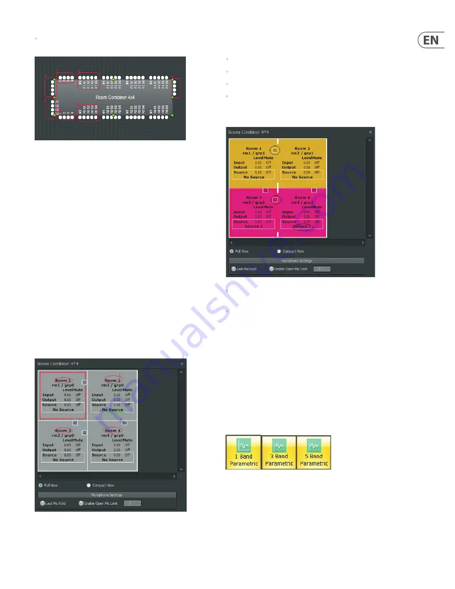
The Room Combiner Component Object can display the following types of input
and output terminals (refer to the numbered items in the screenshot above):
1.
Standard
input terminals. Each room has one input
2.
Auxiliary
audio input terminals. Each room has one auxiliary input, and
each room can select any one of these auxiliary audio inputs.
3.
Logic Input
terminals. Each wall has one logic input terminal. When the
logic input receives a signal from HIGH-to-LOW, the relative wall is removed.
When the logic input received signal from LOW-to-HIGH, the relative wall
is placed.
4.
Logic Output
terminal. Each wall has one logic output. When a wall is
placed (by logic input or by manual set), the related logic output will be
HIGH. When a wall is removed, the related logic output will be LOW.
5.
Logic Input
for Auxiliary Audio Input selection, which can be used to
determine auxiliary audio input.
6.
Logic Output
of Auxiliary Audio Input, which is determined by auxiliary
audio input selection.
7.
Standard
output terminals. Each room has one output.
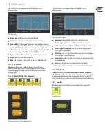
Double-clicking the Room Combiner Component Object produces the following
Control Dialog Box:
Room Combiner Control Dialog Box
This Dialog Box offers the following labels and functions (refer to the
above screenshot):
•
Room Name
can be edited as in #1 in the above screenshot.
•
Wall ID
is visible as in #2 in the above screenshot.
•
Auxiliary Audio
selection is displayed as in #3 above.
•
Last Mic Hold
and
Open Mic Limits
are connected with Auto Mixer.
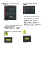
The Room Combiner Dialog Box also shows information about combined rooms
and walls:
•
Room 1 and Room 2 have been combined into Group 1 (shown as “grp1”,
please see the gold group). Wall 01 has been opened to combine the rooms.
•
Room 3 and Room 4 have been combined into Group 2 (shown as “grp2”,
please see the hot pink group). Wall 03 has been opened to combine
the rooms.
3.3 equalisers
Equaliser
modules provide both graphic and parametric equalisation, as well as
feedback suppression. Equalisers may be connected between any components
within the Build Window, for applications which require room equalization,
tone adjustment, or feedback control. Equalisers appear in pre-defined
configurations, but these configurations may be customized when placing
modules from the Module Library Toolbar.
3.3.1 Parametric equaliser
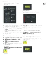
Parametric Equaliser
offers standard parametric functionality.
Parametric Equaliser Module Icons
Summary of Contents for DM8000
Page 65: ......


