PAS SERIES
Remote Control 4-17
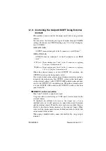
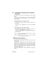
4.1.6 Controlling the Output ON/OFF Using External
Contact
This method is used to control the output on/off status using external
contacts.
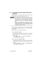
You can select the following two types of modes through CONFIG
settings. For details on CONFIG settings, see "3.2.4 Unit Configura-
tion (CONFIG)".
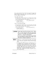
LOW=ON mode
OUTPUT turns on when pin 3 of the J1 connector is set LOW level
*1
.
HIGH=ON mode
OUTPUT turns on when pin 3 of the J1 connector is set HIGH
level
*2
.
*1
LOW level: Means shorting pins 2 and 3 of the J1 connector, or applying
0 V to pins 2 (common) and 3.
*2
HIGH level: Means opening pins 2 and 3 of the J1 connector, or applying
3.5 V to 5 V to pins 2 (common) and 3.
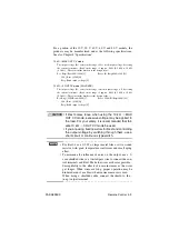
When the external contact is in the OUTPUT ON condition, the
OUTPUT switch on the front panel is valid.
If you wish to turn on the output using external contact after you have
turned off the output using the OUTPUT switch on the front panel,
set the external contact to the OUTPUT OFF condition once and then
set it to the OUTPUT ON condition again. When the external contact
is in the OUTPUT OFF condition, the OUTPUT switch on the front
panel is invalid.
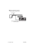
■
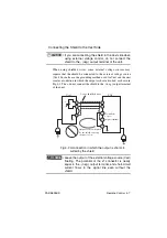
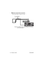
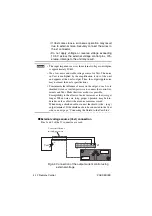
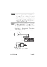
ON/OFF control connection
Pins 2 and 3 of the J1 connector are used.
Use parts with a contact rating of 5 VDC and 10 mA or more for the
external contact.
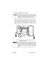
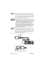
To minimize the influence of noise on the output, use a 2-core
shielded wire or a twisted-pair wire to connect the control terminals
and the external contact. Make the wires as short as possible. Suscep-
tibility to the effects of noise increases as the wires get longer. When
wires are long, proper operation may be hindered even if a cable with
anti-noise measures is used.
When using a shielded cable, connect the shield to the - (neg.) output
terminal.
Summary of Contents for PAS 10-105
Page 10: ...VIII PAS SERIES This page has been intentionally left blank ...
Page 54: ...3 22 Basic Operation PAS SERIES This page has been intentionally left blank ...
Page 78: ...4 24 Remote Control PAS SERIES This page has been intentionally left blank ...
Page 131: ...PAS SERIES Specifications 8 13 This page has been intentionally left blank ...
Page 137: ...PAS SERIES Specifications 8 19 This page has been intentionally left blank ...
Page 145: ......

