

5-10 Parallel and Series Operation
PAS SERIES
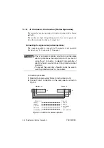
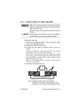
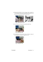
5.2.2 J1 Connector Connection (Parallel Operation)
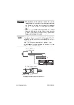
For master-slave parallel operation, two units are connected as shown
in Fig.5-6.
The maximum output current during master-slave parallel operation
is equal to the number of units connected in parallel multiplied by the
rated output current of a single unit.
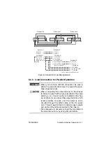
Connecting the signal wires (parallel operation)
The connector needed to connect the J1 connector is not provided.
For detail, see "4.1.1 About the J1 Connector" .
• The J1 connector contains pins that are at the same
electric potential as the output terminal. If you are not
using the J1 connector, to prevent the possibility of
electric shock, be sure to insert the protective socket
provided.
• To prevent the possibility of electric shock, be sure to
use the protective cover on the sockets.
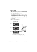
Connection procedure
1.
Decide the power supply that is to be the master unit.
2.
Connect the J1 connectors on the rear panel as shown in
Fig.5-6.
When connecting more than two slave units, repeat the steps for
connecting slave units 1 and 2.
WARNING
Summary of Contents for PAS 10-105
Page 10: ...VIII PAS SERIES This page has been intentionally left blank ...
Page 54: ...3 22 Basic Operation PAS SERIES This page has been intentionally left blank ...
Page 78: ...4 24 Remote Control PAS SERIES This page has been intentionally left blank ...
Page 131: ...PAS SERIES Specifications 8 13 This page has been intentionally left blank ...
Page 137: ...PAS SERIES Specifications 8 19 This page has been intentionally left blank ...
Page 145: ......