PAS SERIES
Basic Operation 3-5
4.
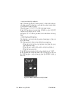
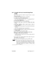
Press the OVP switch.
The voltage display shows the preset value, and the current dis-
play shows "OVP."
5.
Press the VOLTAGE switch to select Coarse or Fine (preset
digit).
6.
Turn the dial to set the OVP trip point.
Next, we will check the operation. Proceed to step 7 .
7.
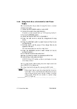
Press the OVP switch to escape from the OVP setup mode.
8.
Press the SET switch to enter the output setup mode.
SET switch lights.
9.
Press the VOLTAGE switch and set the output voltage to a
value significantly less than the OVP trip point voltage.
10.
Press the OUTPUT switch to illuminate OUTPUT ON.
11.
Gradually turn the dial clockwise, and check that the OUT-
PUT turns off or the POWER switch trips when the output
voltage reaches the preset OVP trip point voltage.
When the POWER switch is not set to trip when the protection
circuit is activated in CONFIG, ALM lights in the display section
and the voltage display shows "OVP."
We are done setting the OVP trip point.
You can set or confirm the OVP trip point even when OUTPUT is
turned on. In this case, if the OVP trip point voltage is set lower than
the preset output voltage, OVP is activated and the OUTPUT turns off
or the POWER switch trips.
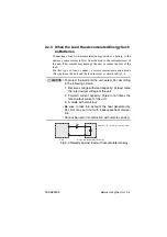
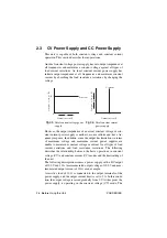
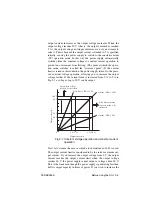
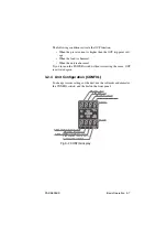
The following conditions activate the OVP function.
• When the preset voltage is higher than the OVP trip point voltage.
• When the sensing wire comes loose.
• When the load is abnormal.
• When the unit is abnormal.
If you turn on the POWER switch without correcting the cause, OVP
is activated again.
Summary of Contents for PAS 10-105
Page 10: ...VIII PAS SERIES This page has been intentionally left blank ...
Page 54: ...3 22 Basic Operation PAS SERIES This page has been intentionally left blank ...
Page 78: ...4 24 Remote Control PAS SERIES This page has been intentionally left blank ...
Page 131: ...PAS SERIES Specifications 8 13 This page has been intentionally left blank ...
Page 137: ...PAS SERIES Specifications 8 19 This page has been intentionally left blank ...
Page 145: ......

