3-20 Basic Operation
PAS SERIES
1.
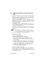
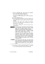
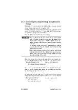
Press the POWER switch while pressing the CONFIG
switch to enter the CONFIG setting mode.
Turn on remote sensing through CONFIG setting.
For details on CONFIG settings, see "3.2.4 Unit Configuration
(CONFIG)".
2.
Turn off the POWER switch.
3.
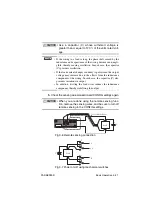
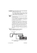
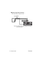
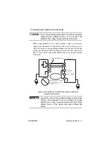
As shown in Fig.3-6, connect the sensing wires between the
sensing terminals and the load cable by using the screws
provided.
To decrease output ripple voltages resulting from inductive
effects, use a 2-core shielded wire for the sensing wires. Connect
the shield to the - (neg.) terminal.
If you cannot use shielded wires, twist the + (pos.) and - (neg.)
wires thoroughly.
• For sensing cables, use cables with a higher voltage
rating than the isolation voltage of the unit. For
details, see "2.5 Grounding the Output Terminal"
Protect the uncovered section of the shielded wire by
using insulation tubes with a withstand voltage
greater than the isolation voltage of the unit.
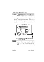
• To turn on/off the power supplied to a load using a
mechanical switch, provide additional switches
between the sensing wires as shown in Fig.3-7 and
turn on/off the power and remote sensing cables
simultaneously. Be sure to turn off the OUTPUT
switch or POWER switch before turning on/off the
mechanical switch.
•
If the sensing wires come loose, the output voltage
across the load cannot be stabilized and may cause
excessive voltage to be applied to the load. Securely
connect the sensing wires such as by using crimp ter-
minals.
4.
As necessary, connect an electrolytic capacitor (C) between
0.1 µF to several hundred µF across the load terminals.
WARNING
CAUTION
Summary of Contents for PAS 10-105
Page 10: ...VIII PAS SERIES This page has been intentionally left blank ...
Page 54: ...3 22 Basic Operation PAS SERIES This page has been intentionally left blank ...
Page 78: ...4 24 Remote Control PAS SERIES This page has been intentionally left blank ...
Page 131: ...PAS SERIES Specifications 8 13 This page has been intentionally left blank ...
Page 137: ...PAS SERIES Specifications 8 19 This page has been intentionally left blank ...
Page 145: ......

