8163A/B, 8164A/B, 8166A/B User’s Guide
227
Setting Attenuation and/or Power Levels
8
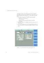
• To zero all the powermeters hosted by the same mainframe as the
Attenuator module (including the Attenuator module and, for example,
the powermeter incorporated in a return loss module), press [Menu] ,
then select <
Zero All
>.
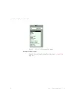
• To set the measurement Averaging Time used by the powermeter
incorporated in the Attenuator module, press [Menu] , select
<
Averaging Time
>, press [OK], select your preferred Averaging Time,
press [OK], then press [Close].
• As with any powermeter, a longer Averaging Time increases accuracy
and noise rejection, but increases response time.
Calibration Procedure
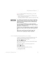
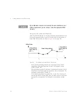
The power level measured by the integrated powermeter at the output of
the module is displayed as P
actual
. To calibrate your test setup, you apply a
P
Offset
to calibrate for the patchcord and connector losses that occur
between the Attenuator module output and the DUT input.
After calibration, you edit the Attenuator’s P
SET
parameter to control the
absolute power applied to the DUT.
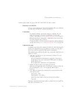
1 Disconnect the DUT input in your test setup and connect it to your
reference powermeter.
•
Set the
λ
parameter for the reference powermeter to the source
wavelength or, for a multi-wavelength DWDM signal, the effective
wavelength
λ
effective
Refer to
•
Set an appropriate measurement <
Averaging Time>
.
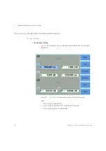
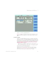
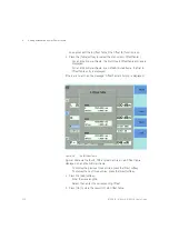
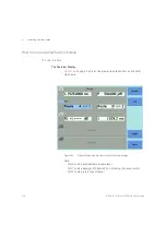
2 Display the details screen for the Attenuator module.
•
Make sure the
λ
parameter set for the Attenuator module matches
the source wavelength or, for a multi-wavelength DWDM signal,
λ
effective
.
•
Make sure that the Averaging Time set for the integrated
powermeter matches that set for the reference powermeter.
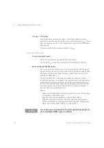
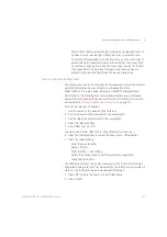
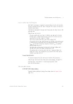
3 If the reference powermeter is hosted by the same mainframe as the
Attenuator module:
•
Select the P
Offset
field,
•
Press the [PM-> Off ] softkey,
•
Select the channel used to host your reference powermeter,
•
Press [OK].
Summary of Contents for 8163A
Page 17: ......
Page 86: ...8163A B 8164A B 8166A B User s Guide 85 Additional Information 2 Figure 47 MAC Address...
Page 99: ......
Page 133: ......
Page 213: ......
Page 298: ...8163A B 8164A B 8166A B User s Guide 297 Applications 10 Figure 183 Low Dynamic Range...
Page 310: ...8163A B 8164A B 8166A B User s Guide 309 Applications 10 Figure 190 Printed Results...
Page 313: ......
Page 345: ......
Page 453: ......

