


GB - 35
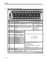
Parameter Description
5
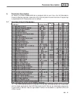
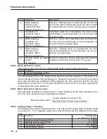
DC link voltage CP.07
0…1000 V
6
apparent current CP.04
0…2 • rated current
7
active current ru.17
0…2 • ±rated current
8…10 reserved
–
11
absolute active current ru.17
0…2 • rated current
12
power stage temperature ru.38
0…100 °C
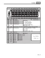
13…21 reserved
–
22
Analog input before amplification (ru.27)
0…100 %
23
Analog input after amplification (ru.28)
0…400 %
24…25 reserved
–
26
Active power ru.81
0…±2 • Rated power
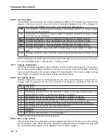
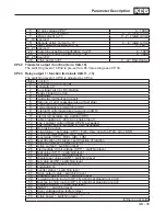
CP.32 Transistor output / function (term. X2A.10)
The switching level of CP.32 is pre-set to 4.00. Value range see CP.33.
CP.33 Relay output 1 / function (terminals X2A.11...13)
The switching level of CP.33 is adjusted by CP.34.
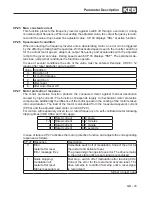
Value Function
0
No function (generally off)
1
Generally on
2
Run signal; also by DC-braking
3
Ready signal (no error)
4
Fault relay
5
Fault relay (without auto-reset)
6
Warning or error message (also at fast stop)
7
Overload pre-warning (OL)
8
Overtemperature pre-warning (OH)
9
External Overtemperature pre-warning (dOH)
10
Motor protection pre-warning (OH2)
11
Interior temperature pre-warning (OHI)
12
Cable breakage 4...20 mA on analog input 1
14
max. constant current (Stall, CP.25) exceeded
15
max. ramp current (LA-Stop, CP.24) exceeded
16
DC-braking active
20
Actual value = set value (CP.3 = Fcon; rcon; not at noP, LS, error, SSF)
21
Accelerate (CP.3=FAcc, rAcc, LAS)
22
Decelerate (CP.3 = FdEc, rdEc, LdS)
23
Real direction of rotation = set direction of rotation
24
Utilization (CP.6) > switching level
25
Active current > switching level
26
Intermediate circuit voltage (CP.7) > switching level
27
Real value (CP.1) > switching level
28
Set value (CP.2) > switching level
31
Absolute set value at AN1 > switching level
34
Set value at AN1 > switching level
40
Hardware current limit activated
41
modulation on
44
Inverter status > switching level
47
Ramp output value > switching level
48
Apparent current (CP.4) > switching level
49
Forward running (not at nOP, LS, abnormal stopping or error)
50
Reverse running (not at nOP, LS, abnormal stopping or error)
63
Absolute ANOUT1 > switching level
65
ANOUT1 > switching level
70
Driver voltage active (safety relay)
73
Absolute active power > switching level
74
Active power > switching level
further on next side
Summary of Contents for COMBIVERT G6 series
Page 1: ...C O M B I V E R T Mat No Rev 00G6NEM DC00 1G GB Installation Manual Housing C Power 5 5 11kW...
Page 2: ......
Page 4: ...GB 4 Table of Contents...
Page 37: ...GB 37 Parameter Description...
Page 41: ...GB 41 Notes...