


GB - 23
Control
4.
Control Circuit Analog/Digital
The control circuit provides the following analog and digital functions:
•
Hardware allocation of digital and analog inputs and outputs.
•
Diagnostic interface (parameter display, scope mode)
•
Hardware of the control circuit „safety separated“ according to EN 61800-5-1 (base TN-
C/-S mains)
•
Operation and diagnosis via LCD display and 8 keys keyboard or error LED.
•
Provide Allocation of power module parameters for the parameterization for not supplied
voltage power module.
•
Safety function (two channel torque off)
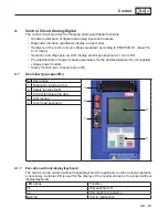
4.1
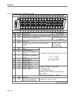
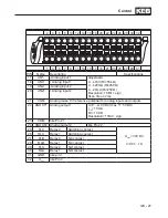
Overview (type-specific)
No. Description
3
2
1
4
5
1
2
31
32
1 Diagnostic interface X4A
2 Safety function X2B
3 Control terminal strip X2A
4 LCD display
5 Touch pad keyboard
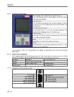
4.1.1 Execution without display/keyboard
The control can be ordered without display/keyboard for applications when no local operation
is necessary. A status LED is used for the display of the inverter status for the variant without
display/keyboard.
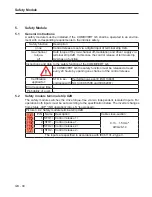
LED status
Function
off
Unit switched off
on
Unit ready for operation
flashing
Unit in malfunction
Summary of Contents for COMBIVERT G6 series
Page 1: ...C O M B I V E R T Mat No Rev 00G6NEM DC00 1G GB Installation Manual Housing C Power 5 5 11kW...
Page 2: ......
Page 4: ...GB 4 Table of Contents...
Page 37: ...GB 37 Parameter Description...
Page 41: ...GB 41 Notes...