


GB - 30
Safety Module
5.
Safety Module
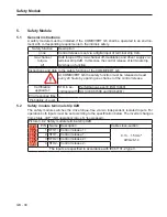
5.1
General instructions
A safety module must be installed, if the COMBIVERT G6 shall be operated in an environ-
ment with corresponding requirements to the intrinsic safety.
Safety function
Description
none
Control release is set via a digital input of terminal strip X2A.
two-channel
torque-
off
Safe torque off by two-channel off-modulation and driver supply via
terminal strip X2B. In this case the control release of terminal strip
X2A has no function.
Instructions and data to the safety function of the COMBIVERT G6
At COMBIVERT G6 the safety function must be released at least
every 24 hours by opening one channel of the control release.
Certification
applied for:
STO in ac-
cordance with
Performance-Level E (ISO 13849)
SIL3 (IEC 61508 and IEC 62061)
Error response time –
Probability of a jerk –
5.2
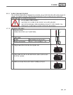
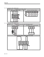
Safety module terminal strip X2B
The safety module switches the drive torque-free via two independent, isolated inputs. For
operation both inputs must be set according to the specification below. The inverter changes
from status „nOP “(NO operation) into „LS “(Low speed).
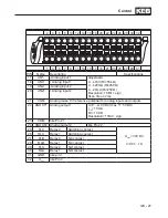
Picture 3.4.2 Safety module terminal strip X2B
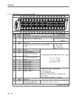
PIN Name Description
Cable cross-section
1 STO1+ Control release 1 +
0.13…1.5 mm²
AWG26-14
2 STO1- Control release 1 -
3 STO2+ Control release 2 +
4 STO2- Control release 2 -
The inputs are specified in accordance with IEC61131-2 type 3.
Summary of Contents for COMBIVERT G6 series
Page 1: ...C O M B I V E R T Mat No Rev 00G6NEM DC00 1G GB Installation Manual Housing C Power 5 5 11kW...
Page 2: ......
Page 4: ...GB 4 Table of Contents...
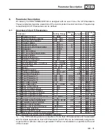
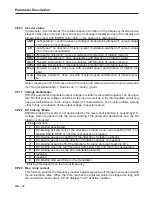
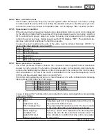
Page 37: ...GB 37 Parameter Description...
Page 41: ...GB 41 Notes...