


GB - 21
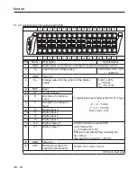
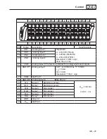
Connection of the Power Unit
mixed sensor chain
T1
T2
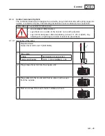
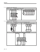
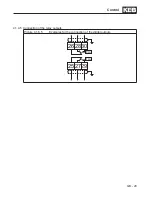
3.2.5 Wiring example
3.2.5.1 Wiring example with extensive fire protection
S2
S1
L1
L2
L3
K1
K1
K1
2
L1 L2 L3
1
4
3
6
5
12
11
14
13
G
++ PB
OH1
OH2
PE
F
I1 COM
RB
+24VDC
Power circuit
Control circuit
F Main fuses
S1 Push-bottom switch for switch on
K1 Line contactor with auxiliary contacts
S2 Emergency-off switch
G KEB COMBIVERT G6
RB Braking resistor with temperature moni-
toring
3.2.5.2 Note to the function
In the example above the locking of the line contactor K1 is interrupted in case of overheating
of the braking resistor. The line contactor drops and switches off the mains voltage. The au-
xiliary contacts 13/14 open the error linkage circuit at terminals I1/COM and release an error.
The modulation is switched off. Thus the drive in generatoric operation does not regenerate
further energy into the DC link circuit.
Summary of Contents for COMBIVERT G6 series
Page 1: ...C O M B I V E R T Mat No Rev 00G6NEM DC00 1G GB Installation Manual Housing C Power 5 5 11kW...
Page 2: ......
Page 4: ...GB 4 Table of Contents...
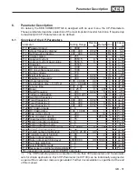
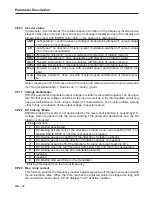
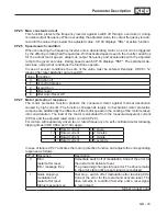
Page 37: ...GB 37 Parameter Description...
Page 41: ...GB 41 Notes...