


GB - 13
Mechanical Installation
2.3.3 Control cabinet installation
The power loss for the control cabinet dimension is to be taken from the technical data.
Mounting distances
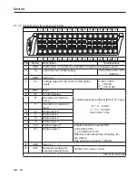
Dimensi-
on
Distance in mm
Distance in
inch
C
A
B
D
D
A
150
6
B
100
4
C
30
1,2
D
0
0
X
1)
50
2
1) Distance to preceding elements in the cabinet
door.
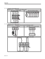
If construction-conditioned the control cabinet cannot be without indoor ventilation, appropri-
ate filters must avoid suction of foreign objects.
Direction of the
air flow
Front and side view of the coolant inlet
Coolant outlet
Coolant inlet
Summary of Contents for COMBIVERT G6 series
Page 1: ...C O M B I V E R T Mat No Rev 00G6NEM DC00 1G GB Installation Manual Housing C Power 5 5 11kW...
Page 2: ......
Page 4: ...GB 4 Table of Contents...
Page 37: ...GB 37 Parameter Description...
Page 41: ...GB 41 Notes...