


GB - 27
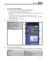
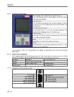
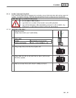
Control
2
4
6
8 10 12 14 16 18 20 22 24 26 28 30 32
1
3
5
7
9 11 13 15 17 19 21 23 25 27 29 31
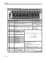
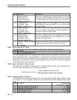
PIN
Name
Description
Specifications
17
AN1-
-Analog input 1
adjustable:
0…±10
V (Ri=55 kΩ)
0…±20
mA (Ri=250 Ω)
4…20
mA (Ri=250 Ω)
Resolution: 10 Bit + sign
Scan time ≤ 2 ms
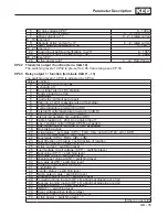
18
AN1+
+Analog input 1
19
AN2-
-Analog input 2
20
AN2+
+Analog input 2
21
COM
Analog mass; 0V reference potential for analog inputs and outputs
22 ANOUT1 Analog output 1
U=0…±10 VDC (max. 11.5 VDC)
I
max
=10 mA
Ri = 100 Ω
Resolution= 11Bit + sign
23
COM
like Pin 21
24 ANOUT2 Analog output 2
like Pin 22
25
FLC
Relay 2
Switching contact
U
max
= 30 V DC
I = 0.01…1 A
26
RLC
Relay 1
Switching contact
27
FLB
Relay 2
NC contact
28
RLB
Relay 1
NC contact
29
FLA
Relay 2
NO contact
30
RLA
Relay 1
NO contact
31
GND
like pin 1
32
U
out
like Pin 4
Summary of Contents for COMBIVERT G6 series
Page 1: ...C O M B I V E R T Mat No Rev 00G6NEM DC00 1G GB Installation Manual Housing C Power 5 5 11kW...
Page 2: ......
Page 4: ...GB 4 Table of Contents...
Page 37: ...GB 37 Parameter Description...
Page 41: ...GB 41 Notes...