


GB - 24
Control
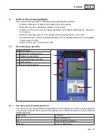
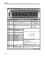
4.1.2 Keyboard and display
LCD display, 160 x 160 pixel, 32 levels of grey
The LCD display offers a clear display of the information
with plain text display.
Function strip
The function strip displays the actual possible functions
of the keys F1 to F4. A flashing function strip indicates an
inverter error.
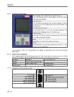
Function keys F1 to F4
The function keys F1 to F4 are variable assigned. The
assignment is displayed by the function key.
Up and Down
With "▲" and "▼" you can move between the menu items
or change parameter values.
ESC
With ESC you reach the upper level menu.
Enter
With ENTER you reach the selected menu item or a se-
lection can be confirmed.
The operation of the unit via keyboard and display is described in the manual „PLF501B-
K001.PDF".
4.1.3 Diagnosis/visualisation
The integrated RS232/485 interface serves for the connection of service tools (e.g. COM-
BIVIS) and display. Telegram DIN66019II is used as communication protocol.
Interface
Standard
Connecting cable
RS485
TIA/EIA-485 and ISO 8482
RS232
ANSI TIA/EIA-232
0058025-001D
RS232/USB
0058060-0020
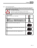
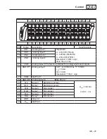
4.1.3.1 Assignment of the interface X4A
5
4
3
2
1
9
8
7
6
5
4
3
2
1
9
8
7
6
reserved 1
6 reserved
TxD (RS232) 2
7 DGND (reference potential)
RxD (RS232) 3
8 TxD-A (RS485)
RxD-A (RS485) 4
9 TxD-B (RS485)
RxD-B (RS485) 5
Summary of Contents for COMBIVERT G6 series
Page 1: ...C O M B I V E R T Mat No Rev 00G6NEM DC00 1G GB Installation Manual Housing C Power 5 5 11kW...
Page 2: ......
Page 4: ...GB 4 Table of Contents...
Page 37: ...GB 37 Parameter Description...
Page 41: ...GB 41 Notes...