SECTION 12
UPS
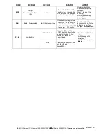
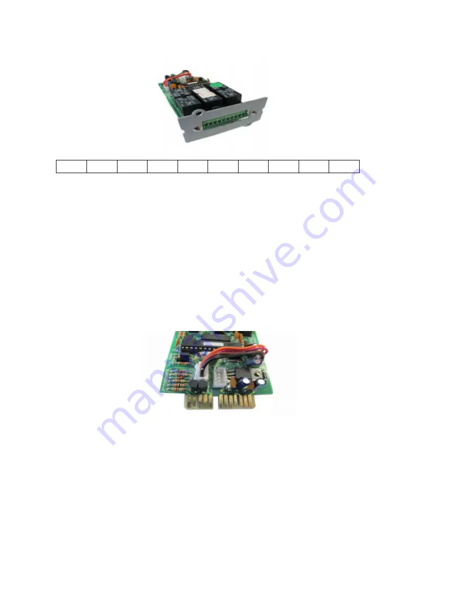
RELAY OUTPUT CARD
PIN ASSIGMENTS
1
2
3
4
5
6
7
8
9
10
1→
UPS ON BYPASS MODE
2→
UTILITY IS NORMAL ( Normally Closed Contact)
3→
UTILITY IS NORMAL ( Normally Open Contact)
4→
INVERTER ON
5→
BATTERY LOW
6→
BATTERY BAD OR FAIL
7→
UPS ALARM
8→
COMMON
9→
SHUT DOWN UPS (+) SIGNAL
10→
SHUT DOWN UPS (-) SIGNAL
An EPO / Emergency shut-down of the UPS may be initiated by ap6 to 25VDC between pins
9 and 10. The shut-down of the UPS will occur in 5 seconds. Each PIN Contact is rated for a
maximum of 25mA.
The Relay Card may also be configured to provide NC or NO contacts. By move the
connector (JP1-5) from 1-2 or 2-3.
Go Section 12.4 on using the ‘NO’ Voltage EPO for immediate OFF.
When using the Relay Outputs. The Inverter On Signal (4) indicates that the UPS is operating normally.
12.2
EMERGENCY POWER OFF/ WITHOUT VOLTAGE
This is small Phoenix Green connector that is inserted in the receiver receptacle located on the front of the UPS,
just below the USB port. This small Green 2 pole connector is inserted into the UPS.
The EPO only requires dry contact closure N/C. The UPS will shut down, including the ability to supply output
power to any type of load. (THE SHUT DOWN HAS A DELAY OF ONLY 1 SECOND)
The UPS will not restart unless the applied signal is changed to N/O. In other words the EPO must be reset or
removed.
NOTE: ALARM CODE ER-000 will be present when the EPO is used or latched.!!
When the applied signal has been removed, the UPS must be reset because this is a latched alarm.
Meaning that you must disconnect the AC and DC, then reconnect and restart the UPS normally..
35
12.1
DBL MX-U Series UPS Outdoors 1000-2000W 120V Manual English
20180312
- This manual is for qualified personnel only


