27
IN
S
T
A
LLIN
G
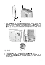
7. Insert the last screw into the third anchor plug through the hole that is on the lower
left side of the motherboard and tighten it. In the meantime, it suffices to drive the
screw deep enough to prevent the cabinet from moving up and down, and prevent
its lower part from getting released from the wall. Jerking the screw might damage
the cabinet.
Figure - 15
IMPORTANT:
1- Parts of the system may be mounted by the system personnel only.
2- The area covered by the front cover is not intended for use; therefore, only the
authorized personnel can open the front cover. Otherwise, the safety conditions
would be violated.
Summary of Contents for MS48IP
Page 1: ...www karel com tr TECHNICAL REFERENCE AND INSTALLATION GUIDE 09 2010 TELEPHONE EXCHANGE...
Page 2: ...MS48IP TECHNICAL REFERENCE AND INSTALLATION GUIDE September 2010...
Page 3: ......
Page 15: ...7 The functional block layout of the cards is shown below Figure 6...
Page 18: ...10 Figure 9 The dimensions of the EXP48 2 6 are 14 5 cm x 16 5 cm and it weighs 0 3 kg...
Page 56: ...www karel com tr TECHNICAL REFERENCE AND INSTALLATION GUIDE 09 2010 TELEPHONE EXCHANGE...

