background image

DCE80-100E

Technical Handbook

Engine TAD720VE

Description

23

P.

Group 30

TDCE01

04GB

The cooling system is equipped with a sensor which activates the 
”Low coolant level” warning lamp on the instrument panel.

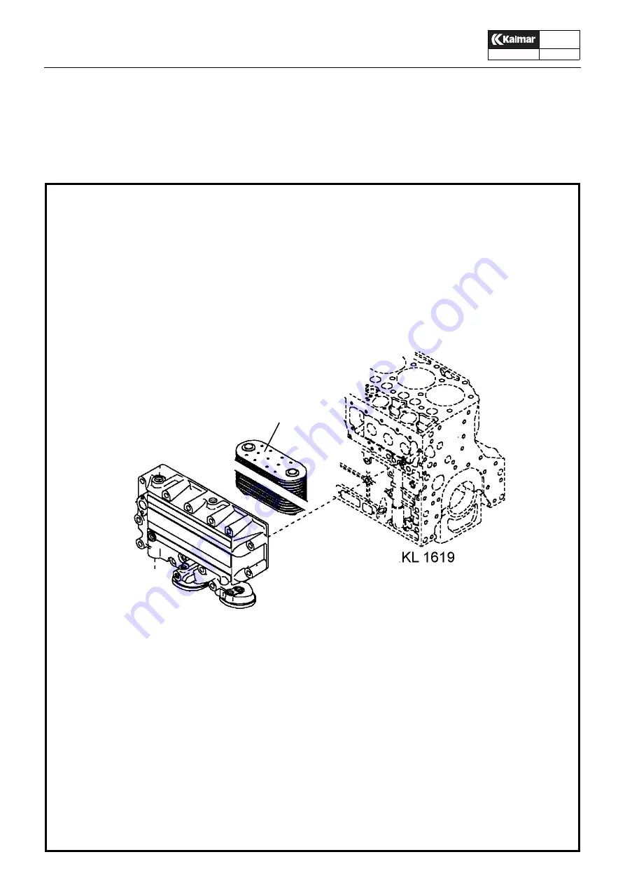
The engine lubricating oil is cooled efficiently and reliably in a 
plate oil cooler.  The gearbox oil is also cooled by the engine cool-
ant, but in a separate shell-and-tube cooler.

1

1. Plate oil cooler

Summary of Contents for DCE80-100E

Page 1: ...80 100E This Handbook deals with the design and maintenance of Kalmar empty container trucks type DCE In addition it gives details of troubleshooting and the most common corrective maintenance Operation and other matters that are primarily of interest to the operator are included in the Instruction Manual Kalmar Industries AB We reserve the right to modify our design and material speci fications w...

Page 2: ......

Page 3: ...s 1 P Group 00 TDCE01 04GB Group 00 Contents Safety regulations 2 General 5 Applications 5 Design 6 Component units 6 Main components 8 Supplementary books 9 Replacement system Spare parts 9 Tools 9 Tightening torques 10 System of units 12 ...

Page 4: ...lps the working process Safety regulations aimed at reducing the risk of personal injury and damage to loads or other property Intended of use z The truck may only be used for the purpose for which it was intended namely to lift and transport goods the weight of which does not exceed the maximum permitted load capacity of the truck z The truck may not without specific permission from Kalmar be mod...

Page 5: ...treme ly careful when working with the hydraulic system and avoid being unnecessarily close to the hy draulic equipment lines and hoses Before work ing on the hydraulic system the accumulators must be emptied into the tank with the help of the special accumulator evacuation valve z Handle batteries and junction boxes with great care The batteries must always be protected over the poles and connect...

Page 6: ...s can cause oil or fluid to penetrate the skin z Under no circumstances may compressed air be used to remove a hydraulic piston from its cylinder z Always attend to damage and wear that may be of significance to the performance and use ful life of the truck or to the safety of the person nel z Follow the safety rules whenever carrying out service work on the air conditioner The re friger ant is in...

Page 7: ...maged and severely rusted components Always select the correct tyre size and construc tion matching the manufacturer s rim or wheel rating and size Do not use over size tyres too large for the rims e g 14 5 inch tyres with 14 inch rims or 16 5 inch tyres with 16 inch rims Never use damaged worn or corroded rims wheels or fitting hardware Always verify that the rim is in a serviceable conditioning ...

Page 8: ...y The operator s cab is provided with vibration isolation and sound insulation and offers excellent all round visibility The operator is provided with many facilities for adjusting his seating attitude The seat backrest and springing of the opera tor s seat can be adjusted in a wide variety of ways The engine is easily accessible through a casing The six cylinder turbocharged engine combined with ...

Page 9: ...ubber suspended 3 Engine six cylinder diesel with turbocompressor 4 Steering axle with pendular suspension and double acting steering cylinder 5 Gearbox combined with torque converter 6 Drive axle with hub reduction and oil sooled hydraulic brake system 7 Carriage with side lift attachment Hydraulically controlled length adjustment and side shift ...

Page 10: ...turdy spring and released by hydraulic oil pressure Tha parking is electri cally activated by a switch in the operator s cab z Hydraulic system with Hydraulic pumps connected to take offs on the torque converter In the standard version the system has one pump for lift and one pump for other working hydraulics Some machines have a separate system for side lift which is then fed by a separate pump T...

Page 11: ...alogue Instruction Manual for engine Workshop Manual för Engine Replacement system Spare parts Kalmar operates a system of replacement parts repair kits and gasket sets covering most of the vital components of the truck For the contents of these kits see the Spare parts catalogue Tools Kalmar offers a wide range of tools for truck maintenance work For further information please contact Kalmar s se...

Page 12: ...able 1 should be reduced by approx 5 due to the increased scatter and to prevent the bolt from being tightened beyond its yield point Surface treatment Condition Lubriation Bolt Nut 1 untreated untreated oiled 2 bright galvanised bright galvanised bright galvanised untreated bright galvanised bright galvanised dry or oiled 3 hot dip galvanised bright galvanised dry or oiled Quality 8 8 10 9 12 9 T...

Page 13: ...tightened to the specified torque Quality 8 8 10 9 12 9 Tightening torque Nm Condition Thread M 1 2 3 1 1 4 5 6 8 10 3 2 6 4 11 26 52 2 9 5 7 9 8 24 47 3 6 7 2 12 5 30 59 4 6 9 1 16 38 74 5 5 11 19 45 89 12 16 20 24 30 91 220 430 750 1480 81 198 386 668 1317 103 250 49 848 1672 128 313 620 1050 2080 154 375 732 1270 2500 Quality 8 8 10 9 12 9 Tightening torque Nm Condition Thread UNC 1 2 3 1 1 1 4...

Page 14: ...16 5 8 3 4 7 8 1 1 1 8 1 1 4 1 3 8 1 1 2 164 227 396 629 937 1350 1860 2500 3260 145 202 352 560 834 1200 1655 2225 2900 185 256 447 710 1058 1525 2100 2825 3680 231 321 559 889 1320 1900 2630 3530 4610 273 379 661 1050 1560 2250 3110 4170 5450 megapascal bar Kilogram force per square centimetre kpf cm Atmosphere at Pound force per square inch psi 1 0 1 0 098 10 1 0 98 10 2 1 02 1 145 14 5 14 2 Ne...

Page 15: ...d cab Specifications 2 Chassis 3 Description 3 Operator s cab 4 Description 4 Steering column 7 Service 8 Changing the fresh air filter 8 Check and lubrication of brake pedal 8 Windscreen wipers 9 Air conditioning unit 10 Description 10 Service 13 Checking the air conditioning unit 13 ...

Page 16: ... Electric power consumption approx 350 W z Compressor Max speed 4000 r min Refrigerant R134a Electric power consumption approx 50 W Oil capacity Zexel PAG SP 20 1 5 dl z Condenser Electric power consumption 250 W z Cooling effect 6 8 5 kW z Heating effect approx 11 kW Refrigerant R12 is no longer in production due to legislation ...

Page 17: ...ight z The hydraulic oil tank and the fuel tank are produced as sep arate units and are bolted to the side of the chassis The tanks have a low profile which contributes to the good visi bility z Separate mounting for cab attached with screws to the chassis Two different heights are available Steps and plat form on the left hand side optional also right hand side 1 Mounting for mast 2 Mounting for ...

Page 18: ... opera tor comfort Effective insulation minimises the vibrations and sound level in the cab The standard heating system consists of a fan and heater for heating the air in the cab by recirculation Fresh air is drawn in through a ventilation air filter Full air conditioning with cooling heating and dehumidification is available to special order 1 Steering column with instrument panel and switches E...

Page 19: ...a Lift b Tilt c Sideshift d Length adjustment 20 40 e Locking Unlocking twist locks 7 Electrical central unit with fuses and relays 8 Brake pedals normal driving brake 9 Release clutch 10 Accelerator pedal 11 Steering wheel adjustment 12 Operator s seat 13 Parking brake 14 Emergency switch for all hydraulic functions 15 Key switch for by passing safety system KL743 7 1 2 3 4 N R F 1 4 5 2 3 R 0 L ...

Page 20: ...l cold 1 40 Switch with lamp DIAGNOSIS QSB5 9 41 a Warning lamp STOP ENGINE QSB5 9 b Indicating lamp CHECK ENGINE QSB5 9 42 Warning lamp battery charging 43 Warning lamp low engine oil pressure 44 Warning lamp low gearbox oil pressure 45 Warning lamp low brake pressure accumulator pressure 46 Warning lamp low engine coolant level 47 Indicating lamp preheating 48 Warning lamp high engine coolant te...

Page 21: ...th the ECS terminal At the very foot of the steering column is the steering valve Orbitrol activated by the steering wheel via an angled gear The steering column is equipped with an adjustment handles for the alteration of steering wheel height and rake KL1751 KL1752 KL580A 1 2 3 4 N R F 1 4 5 2 3 R 0 L 1 2 3 4 5 Steering column 1 Gear lever 2 Multi function lever 3 ECS terminal 4 Steering wheel a...

Page 22: ...r by using a high pressure washer Replace the insert if necessary 3 Reinstall the filter insert Checking condensate draining 1 On certain machines with air conditioning system there are two hoses for draining of condensate from the condensor The hoses can be found on the underside of the cab s front see illustration 2 Check that the hoses are hanging so that there can be no water accumulation A be...

Page 23: ...B Check and lubrication of brake pedal every 1000 hours 1 Check and tighten the locking screws 3 so that the brake pedal is securely fitted in the console 2 Lubricate the brake pedal shaft through the nipples 2 1 Brake pedal 2 Lubricating nipple 3 Locking screw 4 Shaft 1 2 3 4 ...

Page 24: ...e arms to and fro Fitting 1 Check to ensure that the splines on the motor shaft are free from the softer material from the wiper arm mounting If this is not the case clean the splines so that they can pressed fully into the wiper arm mounting 2 Fit the wiper arms onto the motor shafts and tighten the nuts to a torque of 16 20 Nm Hold the wiper arm to take up the torque pressure so that it is not t...

Page 25: ...air when it is cold z dehumidifies the air when it is humid z removes impurities from the air z cools the air when it is warm The equipment is steered by switches and controls on the instru ment panel 1 Heating control 2 Heat exchanger 3 Vapourizer 4 Expansion valve 5 To condenser 6 To compressor 7 Heating valve 8 From engine 9 To engine 10 Fan 11 Fan 12 Fan control 13 Fresh air filter 14 Air disp...

Page 26: ...1 04GB 1 Liquid receiver filter dryer 2 Evaporator 3 Fan 4 Expansion valve 6 Condenser 7 Compressor A High pressure gas B High pressure liquid C Low pressure liquid D Low pressure gas E Warm air in cab F Cooled air to the cab G Outside air for removing heat F E C E D 2 3 4 A B 7 6 G 1 ...

Page 27: ...The function of the liquid receiver with integrated filter dryer is to collect the liquid coolant bind the moisture and to filter and re move impurities The receiver which is located in the condenser housing also serves as the expansion vessel in the refrigeration circuit After flowing through the dryer in the bottom of the liquid receiver the refrigerant flows through a riser tube A sight glass e...

Page 28: ...ditioner At an outdoor temperature below 0 C the system cannot start since the low pressure relay breaks contact 2 After 10 minutes of operation check that no bubbles are visible in the sight glass of the filter dryer Bubbles should occur only when the compressor is started and stopped If there are any air bubbles subsequent filling should be per formed by an authorised service mechanic 3 Check th...

Page 29: ... 5 M M M BR 1 5 BR 1 5 VT 1 5 7 BR 1 5 8 30 85 87 86 GL 1 5 10 LOW IN CAB CLIMATE UNIT CONDENSER UNIT 1 Fan switch 2 Cooler on off 3 Anti freeze thermostat 4 Resistor 5 Fan motor 6 Indicator lamp cold in push button 7 High low pressure monitor 8 Relay 9 Condenser fan 10 Compressor 5 6 9 Circuit diagram in cab climate unit condenser unit HIGH ...

Page 30: ...DCE80 100E Technical Handbook Empty page 16 P Group 10 TDCE01 04GB ...

Page 31: ...oup 20 Electrical system Specifications 2 Electrical system 3 Description 3 Service 5 Checking the electrolyte level of the batteries 5 Fuses 5 Bulbs 5 Relays 6 Sockets in electrical central 7 Electrical diagram explanations 8 List of circuit diagrams 9 Component list ...

Page 32: ...DCE80 100E Technical Handbook Specifications 2 P Group 20 TDCE01 04GB Alternator rating 2240 W Starting battery voltage 2 x 12 V capacity 140 Ah earthing negative ...

Page 33: ...connected to the chassis Warning lamps and instruments are clearly arranged on the in strument panel The central electrical unit with fuses and relays is located on the lower section of the cab s rear wall IMPORTANT Always open the main switch when ever work is to be carried out on the electrical system if the truck is to remain idle for some time and when ever welding work is to be carried out on...

Page 34: ...auge 2 Sensor warning lamp high oil temperatur and gearbox oil temperature gauge 3 Fuse 4 Relay preheater element 5 Sensor coolant temp gauge 6 Sensor high coolant temp warning lamp 7 Sensor engine oil pressure instrument 8 Starter motor 9 Sensor low coolant level warning lamp 10 Engine wiring Electrical components Volvo TWD731VE 1 2 3 4 5 6 7 8 9 10 ...

Page 35: ...ning lamp low oil pressure and gearbox oil pressure gauge 2 Sensor warning lamp high oil temperatur and gearbox oil temperature gauge 3 Sensor coolant temp gauge 4 Solenoid fuel shut off valve 5 Alternator 6 Sensor engine oilpressure 7 Relay preheater element 8 Main fuse 9 Sensor outgoing engine speed 10 Starter motor 2 3 4 5 6 7 8 9 10 ...

Page 36: ...g lamp low oil pressure and gearbox oil pressure gauge 3 Starter motor relay 4 Main fuse 5 Starter motor 6 Sensor coolant temperature gauge 7 Sensor engine oil pressure 8 Generator 9 Sensor warning lamp high oil temperature and gearbox oil temperature gauge 10 Preheater element 11 Sensor outgoing engine speed 12 Solenoid valve housing gearbox 1 2 3 4 5 6 7 8 9 10 11 12 ...

Page 37: ...icators 21 BA15s Position lights 5 SV8 5 Driving lights 75 70 P43t 38 full dipped beam Reversing lights white 70 PK22s Working lights 70 PK22s Hazard beacon 70 PK22s A Main switch N B The starting batteries accompanying the truck are of the maintenance free type which implies that it should not be necessary to top up with electro lyte during the life of the batteries However the level of the elect...

Page 38: ...sing lights reversing alarm 15 15 15 S13 Working lights on mast 15 15 15 S14 Working lights on cabin roof 15 15 15 S15 Container lights 15 15 15 S16 24 12 V converter radio com radio 15 15 15 S17 Stop engine 5 5 S18 El operated parking brake 5 5 5 S19 ECU 1 Aut gearchanging lever steering monitoring 15 15 15 S20 ECU 4 El servo system 15 15 15 S21 Container attachment safety interlock 10 10 10 S22 ...

Page 39: ... Fitted on the engine 2 x 50 A Starting from another battery z Make sure the auxiliary batteries are connected in series so that 24 V will be supplied Note Do not disconnect the truck battery cables z Connect the jumper cables in the following order 1 Red cable to auxiliary battery 2 Red cable to truck battery 3 Black cable to auxiliary battery 4 Black cable to a location some distance away from t...

Page 40: ...ight front 9 X22 Driving lights left rear 9 X23 Driving lights right rear 9 X24 X25 Connector roof 9 X26 Connector chassi 9 X27 Windscreen wiper rear 9 X28 Heating fan windscreen wiper front 9 X29 Horn compressor for air operated seat 9 X30 Sensors under cab 9 X31 X34 Engine gearbox 9 X35 Control motor accelerator ECS 1 9 X36 X37 ECU 1 1 9 X38 Accelerator pedal ECS 1 9 X39 ECU 1 1 9 X40 X41 ECU 1 ...

Page 41: ... G Type of signal H Cable marking A the cable is located inside the central electrical unit J Reference the cable continues on diagram A08333 1000 K Ignition key dependent feed battery 24V L Chassis connection M The cable continues on the same diagram but on another page P3 page 3 N Cable marking the cable is loacted outside the central elec trical unit O Cable colours BK Black BN Brown RD Red OG ...

Page 42: ...ts A35091 0100 Working lights A35092 1100 Cabin A35093 0200 Central lubrication hydraulic fluid cooler 1 A35093 0300 Blinking brakelights when reversing 1 A35093 0400 Autom engine stop alarm function valve All faults after the same set time 1 A35093 0900 Autom engine stop low oil pressure after 6 sec other faults after 25 sec A35094 0100 Side lift attachment Truck Twistlocks A35094 0200 A35094 120...

Page 43: ......

Page 44: ......

Page 45: ......

Page 46: ......

Page 47: ......

Page 48: ......

Page 49: ......

Page 50: ......

Page 51: ......

Page 52: ......

Page 53: ......

Page 54: ......

Page 55: ......

Page 56: ......

Page 57: ......

Page 58: ......

Page 59: ......

Page 60: ......

Page 61: ......

Page 62: ......

Page 63: ......

Page 64: ......

Page 65: ......

Page 66: ......

Page 67: ......

Page 68: ......

Page 69: ...A35093 0200 04 ...

Page 70: ......

Page 71: ......

Page 72: ......

Page 73: ......

Page 74: ......

Page 75: ......

Page 76: ......

Page 77: ......

Page 78: ......

Page 79: ......

Page 80: ......

Page 81: ......

Page 82: ......

Page 83: ......

Page 84: ......

Page 85: ......

Page 86: ......

Page 87: ......

Page 88: ......

Page 89: ......

Page 90: ......

Page 91: ......

Page 92: ......

Page 93: ...mställare fönsterhiss Switch window regulator 112 S Strömställare kylanläggning AC Switch air conditioner AC 113 S Strömställare styrning alt Switch alternative steering 114 S Strömställare läsbelysning Switch reading light 115 S Strömställare instr belysning Switch instrument illumination 116 S Strömställare innerbelysning Switch interior lighting 117 S Strömställare värme Switch heating 118 S St...

Page 94: ... låsn stol Switch interlocking of seat 169 S Strömställare stolsvändning Switch reversible seat 170 S Strömställare förångare LPG Switch evaporator LPG 171 S Strömställare v skiva upp ner Switch fifth wheel up down 172 S Strömställare v skiva fr back Switch fifth wheel forward reverse 173 S Strömställare v skiva skevning Switch fifth wheel levelling 174 S Strömställare utskjut Switch projecting 17...

Page 95: ...act breaking warning lamp air connection 233 S Slutkontakt lampa låsning vändskiva Contact warning interlocking of turntable 235 S Slutkontakt sidoskjutning stol Contact making side shifting of seat 236 S Slutkontakt vattennivå Contact water level 239 S Brytkontakt termisk Contact breaking thermic 240 S Slutkontakt termisk Contact making thermic 241 S Brytkontakt lampa luftmatning släp Contact bre...

Page 96: ...nkers 324 K Relä rangespärr Relay range interlock 325 K Relä blinkande bromsljus back Relay flashing brake lights reversing 326 K Relä blinkande bromsljus runt Relay flashing hazard brake lights 327 K Relä växel neutral Relay gear neutral 328 K Relä växelskifte Relay gear shift 329 K Relä växel hög låg Relay high low gear 330 K Relä startspärr Relay start interlock 331 K Relä drivning fram Relay f...

Page 97: ... attatchment 371 K Relä lyfthöjd Relay liftheight 372 K Relä blinkande varn ljus höjdbegränsn Relay flashing beacon lifting height limiter 373 K Relä bakljus Relay light 375 K Huvudkontaktor reglersystem Main contactor operating control 376 K Kontaktor fram reglersystem Contactor forward operating control 377 K Kontaktor bak reglersystem Contactor reversing operating control 378 K Kontaktor by pas...

Page 98: ... Light bulb side position light right hand rear 420 H G lampa positionsljus vänster Light bulb position light left hand 421 H G lampa positionsljus höger Light bulb position light right hand 422 H G lampa körvisare vä fram Light bulb direction indicator left hand forward 423 H G lampa körvisare hö fram Light bulb direction indicator right hand forwrd 426 H G lampa körvisare vä bak Light bulb direc...

Page 99: ...lysning hytt blackout IR vä Light bulb working light cab blackout IR left 460 E G lampa arb belysning hytt blackout IR hö Light bulb working light cab blackout IR right 461 E G lampa arb bel bom 20 blackout IR vä Light bulb working light boom20 b out IR left 461 E G lampa arb bel bom 20 blackout IR hö Light bulb working light boom20 b out IR right 462 E G lampa arb bel bom 40 blackout IR vä Light ...

Page 100: ...mpa temp spolkrets bromsar Warning lamp temp cooling system brakes 555 H Varn lampa temp kylvatten mot Warning lamp temperature coolant engine 556 H Varn lampa låsning vändskiva Warning lamp interlocking of turntable 560 H Varn lampa temp drivmotor el Warning lamp temperature drive motor 561 H Varn lampa temp pumpmotor el Warning lamp temperature pump motor 562 H Varn lampa öppen twistlock Warning...

Page 101: ...by pass 618 Y M ventil vatten klimatanläggning Solenoid valve water air conditioner 620 Y M ventil vändskiva upp Solenoid valve fifth wheel up 621 Y M ventil vändskiva ner Solenoid valve fifth wheel down 622 Y M ventil vändskiva fram Solenoid valve fifth wheel forward 623 Y M ventil vändskiva bak Solenoid valve fifth wheel rear 624 Y M ventil skevning hö Solenoid valve levelling right hand 625 Y M...

Page 102: ...an hydraulic oil 669 E Värmare kupe motor diesel Heater compartment engine diesel 670 M Kompressor Compressor 671 M Doseringspump diesel Dosage pump diesel 672 M Spjäll motor ECC Draught valve motor ECC 673 Y Vatten ventil motor ECC Water valve motor ECC 674 M Kylfläkt bromsolja Cooling fan brake fluid 675 M Motor Stolsvändning Motor Seat rotation 676 Y Solenoid Broms stolsvändning Solenoid brake ...

Page 103: ...bromsar Transmitter brake flushing circuit 763 B Givare nivå hydraulolja Transmitter hydraulic fluid level 764 B Givare servotryck växellåda Transmitter gear box servo pressure 765 B Givare oljetryck v låda Transmitter oil pressure gear box 766 B Givare oljetemp v låda Transmitter oil temperature gear box 767 B Givare oljetryck motor Transmitter oil pressure engine 768 B Givare oljetryck hydraulik...

Page 104: ... A Kondensor AC fläkt Condensor AC fan 815 S Manöverspak Control lever 820 R Motstånd Resistor 821 C KONDENSATOR CAPACITOR 822 Z Signalfilter Signal filter 823 U Signalomvandlare höger Signal amplifier right 824 U Signalomvandlare vänster Signal amplifier left 825 R Reglage spakstyrning Controls steering with control levers 826 Y Ventil spakstyrning Valve steering with control levers 827 A Växellå...

Page 105: ...nostics on off 1019 S Strömställare rastvärme Switch paus heat 1020 S Strömställare automatisk släpp kläm funktion Switch automatic release clamp funktion 1021 S Strömställare sax Switch extender 1022 S Strömställare vertikalhållning Switch vertical position 1023 S Strömställare låsning övre arm Switch lock upper arm 1024 S Strömställare Korta Armen av på Switch Short Arm on off 1025 S Strömställa...

Page 106: ... Relä arb bel bom 40 vxl std blackout Relay working light boom40 shift std b out 3015 K Relä vxl bromsljus blinkers vä Relay shift brake light direction indicator left 3015 K Relä vxl bromsljus blinkers hö Relay shift brake light direction indicator right 3016 K Relä signalhorn relay horn 3017 K Relä containerbelysning Relay Container light 3018 K Relä containerbelysning IR Relay Container light I...

Page 107: ...ng front legs 6014 Y M ventil fällning bakre ben Solenoid valve lowering rear legs 6015 Y M ventil klämma lossa ben Solenoid valve clamping releasing legs 6016 Y M ventil Hyttskjutning fram Solenoid valve cab movement forward 6017 Y M ventil Hyttskjutning bak Solenoid valve cab movement reverse 6018 Y M ventil spridning ut Solenoid valve spreading out 6019 Y M ventil spridning in Solenoid valve sp...

Page 108: ...on 6054 Y M ventil klämma ihop Solenoid valve clambing in 6055 Y M ventil klämma isär Solenoid valve clambing out 6056 Y M ventil främre knä ut Solenoid valve front knee out 6057 Y M ventil främre knä in Solenoid valve front knee in 6058 Y M ventil bakre knä ut Solenoid valve rear knee out 6059 Y M ventil bakre knä in Solenoid valve rear knee in 6060 Y M ventil främre ben upp Solenoid valve front ...

Page 109: ...Sensor Clamp front legs 7216 S Givare kläm bakre ben Sensor Clamp rear legs 7217 S Givare främnre knä Sensor front knee 7218 S Givare bakre knä Sensor rear knee 7219 S Givare främre ben Sensor front legs 7220 S Givare bakre ben Sensor rear legs 7221 S Givare styraxel Sensor steering axle 7222 S Givare stödben uppe Sensor brace up 7223 S Givare stödben nere Sensor brace down 7224 B Givare mätläge v...

Page 110: ...tation 8086 R Potentiometer sax Potentiometer extender 8087 R Potentiometer klämma Potentiometer clamp 8088 R Potentiometer skevning Potentiometer levelling 8089 R Potentiometer kroklåsning Potentiometer flaps 8090 V Laser pappersaggretgat Lase Pulp an Paper 8091 9000 M Motor höj sänkbar stolspelare Motor rise lower seat column 9001 D Åkerströms fjärrkontroll Åkerströms Remote Control 9002 9003 H ...

Page 111: ......

Page 112: ......

Page 113: ...em 26 Combustion air system 28 Service 30 Coolant quality 30 Lubrication oil quality 30 Draining the water from the fuel tank 30 Inspection of air cleaner and changing insert 30 Changing the oil and oil filter 31 Checking V belt tension 31 Checking and adjusting the valve clearances 32 Changing the fuel filter 33 Preventive maintenance on turbo charger 34 Cummins QSB5 9 See also Cummins Operation ...

Page 114: ...DCE80 100 Technical Handbook Contents 2 P Group 30 TDCE01 04GB ...

Page 115: ...wept volume l 6 73 Valve clearance engine cold inlet mm exhaust mm 0 40 0 55 Idle speed r min adjust so that the engine runs smoothly 650 25 Injection pump timing 10 0 5 BTDC Thermostat starts to open at C fully open at C 75 88 Lubricating oil filter Full flow disposable paper el ement with by pass valve Lubricating oil pressure kPa running speed idling speed 300 500 min 150 Lubricating oil grade ...

Page 116: ...cooler The engine is pressure lubricated by an oil pump which delivers oil to all lubrication points A full flow oil filter effectively cleans the lubricating oil The fuel system is protected against impurities by replaceable filters The engine has replaceable wet cylinder lin ers and two cylinder heads each covering three cylinders The low emission engine has a new design of combustion cham ber i...

Page 117: ...ust manifold 7 Lift eyelet 8 Coolant pipe inlet 9 Pump coupling guard 10 Smoke limiter 11 Oil cooler 12 Fuel shut off valve 13 Injection pump 14 Relay for inlet manifold heater 15 Cable iron 16 17 Coolant pipe outlet 18 Flywheel housing SAE 2 Adaptor for SAE3 19 Starter motor 20 Crankcase ventilation 21 Full flow filter of spin on type 22 By pass filter of spin on type 23 Vibration damper 24 Autom...

Page 118: ...using The coolant then flows to the coolant pump and then into the engine and to the oil cooler When the engine has reached its normal operating temperature the thermostat will open the circuit to the radiator The piston type thermostat is capable of passing a high coolant flow rate at a minimum of pressure drop thus contributing to fa vourable coolant circulation in the engine The coolant pump is...

Page 119: ...nt level warning lamp on the instrument panel The engine lubricating oil is cooled efficiently and reliably in a plate oil cooler that requires no external pipes on the engine The gearbox oil is also cooled by the engine coolant but in a separate shell and tube cooler Thermostat function full coolant circulation Thermostat function during heating up period ...

Page 120: ...o the tank The fuel system includes the following components Fuel tank a separate unit located on the left hand side of the truck The fuel volume in the tank can be read on a gauge on the instrument panel Feed pump of piston type supplies fuel at a certain pressure and flow rate to the injection pump Spill valve which restricts the fuel feed pressure and provides continuous venting of the fuel sys...

Page 121: ... When the starting key is turned to 0 the solenoid valve is deacti vated and the flow is reversed Thereby the feeder pump drains the fuel from the injection pump resulting in engine shut down The check valve prevents return fuel from flowing into the injec tion pump T Inlet from fuel tank F Outlet to fuel pump P Inlet from fuel filter I Outlet to injection pump Fuel shut off valve Normal operation...

Page 122: ...wound paper Injectors each with a nozzle holder and a nozzle When the fuel pressure has risen to the preset value the needle will lift and at omised fuel will be injected into the combustion chamber through accurately calibrated holes in the nozzle sleeve Fuel filter 1 Supply pipe coupling 2 Spill fuel pipe connection 3 Spacers for adjusting the opening pressure 4 Compression spring 5 Thrust pin 6...

Page 123: ...tially the piston temperature which in turn contributes to a longer life of the piston rings re duces the risk of carbon deposits and lowers the oil consumption The pistons are cooled by oil which is sprayed by nozzles into the underside of each piston and into the cooling passages when the piston is at the bottom dead centre Cooling is controlled by a piston cooling valve which shuts off the cool...

Page 124: ...tered oil will flow to the engine The filter is of disposable type and should be scrapped after use By pass filter approx 5 of the oil passes through the by pass filter with very low speed The low speed allows very small parti cles to be separated The filter insert is of the disposable type Crankcase ventilation prevents pressurising of the crank case and collects fuel vapour steam and other gaseo...

Page 125: ...r cleaner the first stage of which collects coarse particles by cyclone action and the par ticles are then collected in a dust receiver The second stage con sists of a filter element the main filter element A safety filter element is located on the inside of the main element The safety element prevents the ingress of impurities into the engine while the main element is being changed and if the mai...

Page 126: ...rbo is cooled in an intercooler The intercooler increases the oxygen supply for combustion so allowing the injected fuel to be burnt more effectively whilst re ducing guel consumption as well as the level of exhaust emis sion Intercooling also reduces the thermal stressed on the engine in creasing durability and reducing oil consumption Inlet manifold heater Before the air is admitted into the com...

Page 127: ...gine may lose power due to insufficient supply of combustion air and engine damage may occur in certain cases The air pipe from the air cleaner to the engine should be checked for tightness from time to time Minor leakage such as that caused by loose hose clips and damaged or porous hoses may cause dust to be drawn into the engine which will give rise to costly engine wear Change the filter elemen...

Page 128: ...e full 5 Lubricate the canister seals with oil 6 Fit the new filters and tighten them by hand only 7 Fill the engine with oil see Group 90 Lubrication chart 8 Run the engine and check that no oil leaks at thefilters 9 Stop the engine and check the oil level after a few minutes Top up as necessary to the MAX level on the dipstick N B To avoid serious damage to the engine use only genu ine Kalmar fi...

Page 129: ...t as necessary Valve clearance 2 Check the oter valves in accordance with the table below Changing the fuel filters 1 Clean the outsides of the filters 2 Remove the filters and discard them 3 Clean the filter head 4 Check that the new filters are perfectly clean and that the seals are in good condition 5 Fit the new filter canisters and tighten them by hand until the seal is in contact with the se...

Page 130: ...ecified intervals Check at regular intervals that the lubricating oil lines to the turbocharger are in good condition and do not leak Also check regularly that the oil pressure is not too low since this could quickly lead to damage to the turbocharger 3 Ensure that the fuel system is serviced at the specified inter vals Inadequate fuel supply caused by clogged fuel filters or incorrect setting of ...

Page 131: ...DCE80 100E Technical Handbook 18 P Group 30 TDCE01 04GB Volvo TAD720VE ...

Page 132: ...r of cylinders 6 Swept volume l 7 15 Valve clearance engine cold inlet mm exhaust mm 0 35 0 55 Idle speed r min adjust so that the engine runs smoothly 700 50 Thermostat starts to open at C fully open at C 87 102 Lubricating oil filter Full flow disposable paper el ement with by pass valve Lubricating oil pressure kPa running speed idling speed 350 min 80 Lubricating oil grade viscosity Se Grupp 9...

Page 133: ...oil pump which delivers oil to all lubrication points A full flow oil filter effectively cleans the lubricating oil An integrated side mounted oil cooler is cooling the entire oil flow The fuel system is protected against impurities by replaceable fil ters To maintain a controlled working temperature in cylinders and combustion chambers the engine is provided with piston cooling The low emission e...

Page 134: ...TAD720VE 28516 1 2 3 4 5 6 7 8 9 10 11 12 13 1 Coolant connection outlet 2 Turbo compressor 3 Manifold 4 Lifting eylet 5 Crankcase ventilation 6 Starter motor 7 Injection pump 8 Oil cooler 9 Generator 10 Oil dip stick 11 Full flow filter of spin on typ 12 Fuel filter of disposable type 13 Fuel pump ...

Page 135: ...be supplied with the same rate of coolant flow The coolant flows in the separate return lines converge into a common pipe in the thermostat housing The coolant then flows to the coolant pump and then into the engine and to the oil cooler When the engine has reached its normal operating temperature the thermostat will open the circuit to the radiator The piston type thermostat is capable of passing...

Page 136: ...em is equipped with a sensor which activates the Low coolant level warning lamp on the instrument panel The engine lubricating oil is cooled efficiently and reliably in a plate oil cooler The gearbox oil is also cooled by the engine cool ant but in a separate shell and tube cooler 1 1 Plate oil cooler ...

Page 137: ...a gauge on the instrument panel Feed pump of piston type supplies fuel at a certain pressure and flow rate to the injection pumps Spill valve which restricts the fuel feed pressure and provides continuous venting of the fuel system The excessive fuel is flow ing through the injection pumps before it is fed through the return line to the fuel cooler and thereafter to the fuel tank Fuel cooler The f...

Page 138: ...yl inder and feed high pressure fuel to the injectors These have an opening pressure of 27 5 MPa When adjustment of the injectors is needed this has to be made separately with shims for every single pump Bränsleförfilter 1 Filter holder 2 Sealing between fil ter holder and filter insert 3 Filter insert washa ble 4 Draining valve for codensate 5 Filter container 6 Sealing ring 1 2 3 4 5 6 1 2 1 Inj...

Page 139: ... differ ent ducts of the lubricating system Piston cooling reduces substantially the piston temperature which in turn contributes to a longer life of the piston rings re duces the risk of carbon deposits and lowers the oil consumption The pistons are cooled by oil which is sprayed by nozzles into the underside of each piston and into the cooling passages when the piston is at the bottom dead centr...

Page 140: ...il will flow to the engine The filter is of disposable type and should be scrapped after use By pass filter approx 5 of the oil passes through the by pass filter with very low speed The low speed allows very small parti cles to be separated The filter insert is of the disposable type Crankcase ventilation prevents over pressure in the crank case and separates fuel mist water mist and other gaseous...

Page 141: ...cles by cyclone action and the par ticles are then collected in a dust receiver The second stage con sists of a filter element the main filter element A safety filter element is located on the inside of the main element The safety element prevents the ingress of impurities into the engine while the main element is being changed and if the main element should sustain damage while the engine is runn...

Page 142: ... the oxygen supply for combustion so allowing the injected fuel to be burnt more effectively whilst re ducing guel consumption as well as the level of exhaust emis sion Intercooling also reduces the thermal stressed on the engine in creasing durability and reducing oil consumption The intercooler is of the air to air type and integrated with the ra diator and the gearbox oil cooler Inlet manifold ...

Page 143: ...gine may lose power due to insufficient supply of combustion air and engine damage may occur in certain cases The air pipe from the air cleaner to the engine should be checked for tightness from time to time Minor leakage such as that caused by loose hose clips and damaged or porous hoses may cause dust to be drawn into the engine which will give rise to costly engine wear Change the filter elemen...

Page 144: ... hand only 7 Fill the engine with oil see Group 90 Lubrication chart 8 Run the engine and check that no oil leaks at thefilters 9 Stop the engine and check the oil level after a few minutes Top up as necessary to the MAX level on the dipstick N B To avoid serious damage to the engine use only genu ine Kalmar filters Checking the V belt tension 1 Check at regular intervals that the V belts are corr...

Page 145: ...nlet valve is just open ing Neither of the push rods can be turned around in this posi tion Cylinder 1 is closest to the flywheel 3 Adjust the valve clearances according to the black markings in the adjoining picture Inlet valve 0 30 mm Exhaust valve 0 50 mm 4 Tighten the lock nut with 20 2 Nm Re check the clearance with a feeler guge 5 Make a chalk mark on every adjusted valve Crankshaft position...

Page 146: ...filter 2 Drain condensate from the filter by opening the draining valve 4 se picture 3 Unscrew the filter container from the filter head 4 Rinse the filter in diesel or replace it if necessary For new filter moisten the new O ring with fuel 5 Fit the filter in the container and fit the O ring 6 Fasten the container to the filter head and tighten it by hand until the O ring is in contact with the s...

Page 147: ...ecified intervals Check at regular intervals that the lubricating oil lines to the turbocharger are in good condition and do not leak Also check regularly that the oil pressure is not too low since this could quickly lead to damage to the turbocharger 3 Ensure that the fuel system is serviced at the specified inter vals Inadequate fuel supply caused by clogged fuel filters or incorrect setting of ...

Page 148: ...Description 35 P Group 30 TDCE01 04GB Cummins QSB 5 9 The following information concerns mainly the specific Kalmar in stallation For general engine information such as system de scriptions diagnosis and error codes refer to the separate Cummins documents ...

Page 149: ...mber of cylinders 6 Swept volume l 5 9 Valve clearance engine cold inlet mm exhaust mm 0 25 0 51 Idle speed r min adjust so that the engine runs smoothly 700 50 Thermostat starts to open at C fully open at C 84 91 Lubricating oil filter Full flow disposable paper el ement with by pass valve Lubricating oil pressure kPa running speed idling speed 310 min 103 Lubricating oil grade viscosity Se Grupp...

Page 150: ...r The engine is pressure lubricated by an oil pump which delivers oil to all lubrication points A full flow oil filter effectively cleans the lubricating oil An integrated oil cooler is cooling the entire oil flow The fuel system is protected against impurities by replaceable fil ters To maintain a controlled working temperature in cylinders and combustion chambers the engine is provided with pist...

Page 151: ...pressor 3 Air cooled manifold 4 Lift eyelet 5 Crankcase ventilation 6 Starter motor 7 Injection pump 8 Oil cooler 9 Alternator 10 Oil dip stick 11 Full flow filter of spin on typ 12 Fuel pre filter with condensate separator 13 Fule lift pump 14 Electroninc control unit 15 Inlet manifold heater 16 Coolant inlet to engine KL1699 15 12 13 7 14 10 5 6 3 2 4 9 1 11 16 ...

Page 152: ...ith a closed cooling system consisting of the following main components z Coolant pump z Radiator with integrated intercooler and gearbox oil cooler z Expansion tank z Thermostat z Radiator fan z Coolant passages z Engine oil cooler N B For further information see Cummins Operation and Maintenance Manual KL1701 A To engine B To engine C To radiator ...

Page 153: ... is circulated in the low pressure system is also cleaned in the fine filters and is returned through a spill valve back to the tank The fuel system includes the following components Fuel tank a separate unit located on the left hand side of the forklift The fuel volume in the tank can be read on a gauge on the instrument panel Feed pump supplies fuel at a certain pressure and flow rate to the inj...

Page 154: ...s and lowers the oil consumption The pistons are cooled by oil which is sprayed by nozzles into the underside of each piston and into the cooling passages when the piston is at the bottom dead centre Reducing valve located just before the filter The valve will open if the lubricating oil pressure is too high and will return ex cess oil back to the sump Oil filter of full flow type with a filter el...

Page 155: ...y cyclone action and the par ticles are then collected in a dust receiver The second stage con sists of a filter element the main filter element A safety filter element is located on the inside of the main element The safety element prevents the ingress of impurities into the engine while the main element is being changed and if the main element should sustain damage while the engine is running e ...

Page 156: ...urbo is cooled in an intercooler The intercooler increases the oxygen supply for combustion so allowing the injected fuel to be burnt more effectively whilst re ducing fuel consumption as well as the level of exhaust emission Intercooling also reduces the thermal stressed on the engine in creasing durability and reducing oil consumption The intercooler is of the water to air type and integrated wi...

Page 157: ... en gine may lose power due to insufficient supply of combustion air and engine damage may occur in certain cases The air pipe from the air cleaner to the engine should be checked for tightness from time to time Minor leakage such as that caused by loose hose clips and damaged or porous hoses may cause dust to be drawn into the engine which will give rise to costly engine wear Change the filter el...

Page 158: ...an oil into the centre of the new filter wait until the oil has seeped through the filter paper and top up until the fil ter are full 5 Lubricate the canister seal with oil 6 Fit the new filter and tighten it by hand only 7 Fill the engine with oil see Group 90 Lubrication chart 8 Run the engine and check that no oil leaks at the filter 9 Stop the engine and check the oil level after a few minutes...

Page 159: ... engine in this position valve clearanc can be checked on following valves 1I 1E 2I 3E 4I and 5E 3 Adjust the valve clearances according to the nominal specifi cations Inlet valve 0 25 mm Exhaust valve 0 50 mm 4 Tighten the lock nut with 24 Nm Re check the clearance with a feeler guge 5 Make a chalk mark on every adjusted valve Crankshaft position 2 6 Rotate the crank shaft another turn 360 7 Adju...

Page 160: ... in fuel sensor from the fitler See picture Discard the old filter 7 Clean the filter head 8 Check that the new filter is perfectly clean and that the seals are in good condition 9 Install the water in fuel sensor into the new filter 10 Lubricate the O ring seal with clean lubricating oil 11 Fit the new filter canister and tighten it by hand until the seal is in contact with the seating surface Th...

Page 161: ...e specified intervals Check at regular intervals that the lubricating oil lines to the turbocharger are in good condition and do not leak Also check regularly that the oil pressure is not too low since this could quickly lead to damage to the turbocharger 3 Ensure that the fuel system is serviced at the specified inter vals Inadequate fuel supply caused by clogged fuel filters or incorrect setting...

Page 162: ......

Page 163: ... Checking pressures in the Clark gearbox 7 Drive axle 7 Description 7 The differential 7 Hub reduction 9 Service brake 9 Parking brake system 10 Releasing the parking brake by mechanical means 10 Service 11 Changing the drive axle oil 11 Installation of disc brake 12 Installing the brake on the axle 14 Installing of hub reduction 16 Dismantling the planet gear 18 Inspection of dismountable rims se...

Page 164: ...atic wear compensation no adjustment All clutches oil cooled and lubricated Stall speed r min 1990 50 Oil filtration Full flow oil filter with safety by pass also strainer screen in sump at bottom of transmission case Drive axle Model Kessler D81 Brake system Wet disc brakes Parking brake system Spring activated disc brake on drive axle input shaft Wheel dimensions in Tyre pressure MPa DCE70 12 00...

Page 165: ... the inside diameter of the pump impeller in the best pos sible way Torque conversion takes place in the oil circuit of the torque con verter When the load on the truck increases i e when the torque required increases the turbine wheel slows down in relation to the pump impeller and the oil flowing through the stator then in creases the torque The output torque gradually increases as the speed of ...

Page 166: ...ical Handbook Transmission Description 4 P Group 40 TDCE01 04GB Gearbox Clark 28000 32000 KEY 1ST 2ND 3RD 1 Turbine wheel 2 Pump impeller 3 Stator 4 Torque converter 5 Oil filter 6 Oil pump 7 Clutch disc 1 2 3 4 5 6 7 ...

Page 167: ...anical gear changing system is available as an option The gearbox has three ratios in each direction and is also provid ed with disengagement which is actuated by a separate inching pedal at the left brake pedal and comes into operation at a certain brake pressure The electrical gear changing system is either manual or automat ical see Group 20 Clark 32000 Gear Activated solenoids F3 F F2 F 2 F1 F...

Page 168: ...raws oil through a suc tion strainer from the gearbox sump and then delivers it through a fine filter to a pressure regulating valve The regulating valve delivers oil at the right pressure to the gear box valve body which actuates the clutch plates for Forward Re verse and 1st 2nd 3rd 4th The clutches use only a small proportion of oil delivered by the pump The remainder is fed through the torque ...

Page 169: ...e topping up with new oil 3 Fit a new gasket to the suction strainer and fit the strainer 4 Unscrew the filter bowl remove the filter and fit a new filter element 5 Fit the new filter and tighten it 6 Fit the drain plugs and tighten them 7 Fill with oil to the MIN mark on the dipstick 8 Start the engine and run it at 500 600 r min until the oil has reached working temperature and the hoses cooler ...

Page 170: ...utch pressure all gears 1 Indicated on the pressure gauge in the cab 2 Parking brake set oil temperature 80 95 C and engine at low idle 3 Shift through all gears and F R The pressure should be 17 20 bar N B In case of incorrect clutch pressure first check the gearbox pressure sensor see picture If more details concerning individual test outlets are re quired contact KALMAR INDUSTRIES SERVICE IMPOR...

Page 171: ...em since the final torque is achieved first at the driven wheels The differential The differential is a simple hypoid type of taper gear drive which means that the centre line of the pinion is offset in relation to the centre line of the crown wheel The pinion is firmly journalled in two robust bearings 1 Parking brake 2 Hub reduction 3 Wet disc brakes 4 Differential 5 Differential gear 6 Crown wh...

Page 172: ...en the drive axle and thereby the sun gear rotates the rotational movement is transmitted to the planet gears Because the ring gear is fixed firmly in the planetary gear carrier hub the planet gears move to wards the ring gear The hub follows this movement and the ro tation is transmitted to the wheels The gear ratio is determined by the number of teeth in the various gears 1 Planet gear 2 Ring ge...

Page 173: ...and rotating with the hub Hydrualic pressure is applied to activate a piston in each hub the discs are then pressed to gether and the wheels are braked The resulting heat caused by friction is led away by the cooling oil circulating in the system Oil from the truck s hydraulic system is used as cooling oil and this gives a high cooling capacity 1 Brake piston 2 Brake discs 1 2 ...

Page 174: ...he adusting screw with a hexagonal socket head wrench and lock the lock nut 11 6 Fasten the lid 12 by hand Releasing the parking brake by mechanical means If the acumulator pressure drops below a certain level the park ing brake is applied automatically If the truck needs to be moved 1 Unscrew the lid 12 2 Loosen the lock nut 11 and unscrew the adjusting screw 7 counter clockwise until the brake p...

Page 175: ... mark at the filling hole hub is horisontal 6 Fill the hub reduction with oil and refit the plug Volume See specifications 7 Repeat for next wheel 8 Remove the level plug from the differential and fill the differ ential with oil Refit an tighten the leel plug Volume See specifications 9 Check oil level an refill as necessary Drive axle oil 1 2 3 2 3 4 1 Differential 2 Drain 3 Fill up level 4 Hub I...

Page 176: ...st diameter is facing downwards Then place the seals in the groove using special installation tapers one large and one small free from any scratches and not lubricated 6 Fit the O ring in the lower groove using an installation taper and push it over the large slide ring with the thinner edge fac ing upwards 7 Fit the O ring in the upper groove using the other installation taper and push it over th...

Page 177: ...e breather 12 with seal 10 and connection 11 12 Screw in the sealing plugs 8 and 18 with seals 9 and 17 13 Move the brake carrier 1 up against the brake housing 2 and screw on securely using screws 7 14 Bleed the brake circuit and then check to make sure the cir cuit is fully sealed When loading with a pressure of 12 MPa for 15 minutes a pressure drop of 2 down to 11 76 MPa is permitted 1 Brake 2 ...

Page 178: ...brake housing 2 using an installation tool Lubricate the sealing ring seat Place the slide ring seal onto the tool the tool presses only on the O ring Push the O ring over the blocking edge unti it snaps into position Lubricate the slide ring 4 Screw the sheel studs 35 into the wheel hub 24 5 Press the taper roller bearing s cones 23 and 25 into the wheel hub 24 N B Do not hit it 6 Fit the slide r...

Page 179: ...e ring gear carrier 7 Fit the ring gear 6 onto the ring gear carrier and secure with screws 11 Fit the ring gear carrier and ring gear onto the axle s splines Turn the ring gear carrier so that the oil flow hole faces down wards Then push the carrier and ring gear into the hub 12 Screw the bearing nuts on and tighten them so that the hub can be turned by hand only with some difficulty Then un scre...

Page 180: ...stallation of hub reduction 1 Press the spacer wahser 1 onto the spindle and seal with LOCTITE 270 2 Push the sun gear 2 onto the spindle and secure with the lock ring 3 Push the input shaft into the hub so that the spacer washer sun gear and lock ring are closely flush with each other ...

Page 181: ...r are opposite each other When the planet gear shafts are pressed in the inner cardboard sleeves in the bearings will be pressed outwards N B The shafts are slightly tapered and cannot therefore be pressed outwards in the other direction as the planetary gear carrier would then be damaged 5 Secure the planet gears with the safety pin 7 6 Install the planetary gear carrier onto the hub 7 Screw the ...

Page 182: ...afety pin out from the inside 2 Press the planet gear shafts out from the outside and in wards in the planetary gear carrier N B The shaft are sligthly tapered and cannot therefore be pressed outwards in the other direction as the planetary gear carrier would then be damaged 3 Remove the planet gear spacer washers bearings ...

Page 183: ...B Group 60 Steering axle Specifications 2 Steering axle 3 Description 3 Service 4 Replacement of steering cylinder 4 Replacement of steered wheel bearings 4 Replacement of knuckle pin bearings 6 Inspection of dismountable rims 8 Safety test when changing tyres 10 ...

Page 184: ...rtain resistance when rotated After tightening of steered wheel bearings the truck should be run for some 100 meters After that the bearing nut should be tightened again to 500 Nm Then the bearing nut must not be loosened Tightening torques Nm kpm Wheel nuts 650 66 Steered wheel bearing nuts 500 51 1 Nuts for upper knuckle pin bearings 500 51 Nuts for lower knuckle pin bearings 500 51 Steering cyl...

Page 185: ...moving parts to minimise the number of service points and to simplify maintenance The mounting in the chassis comprises entirely maintenance free rubber elements The knuckle pins and wheel axles are mounted in taper roller bearings The hydraulic circuits of the steering system are de scribed in Group 70 1 Rubber element 2 Steering cylinder 3 Upper bearing 4 Link lever 5 Lower bearing 6 Knuckle pin...

Page 186: ...o the hub preferably using one of the hub bolts Fit a nut to secure the bolt Use a hand trolley pal let truck or the like for lifting the hub 5 Remove the locknut tab washer and bearing nut The plain washer is loose 6 Remove the hub off the wheel axle by means of the hand truck The inner race of the outer bearing will accompany the hub 7 Withdraw the inner race of the inner bearing from the wheel ...

Page 187: ...uckle pin 9 Protective ring 10 Sealing ring 11 Lower bearing 12 Locking ring 13 Shims 14 Bearing holder 15 Steering cradle 16 Lubricating nipple 17 Spindle 18 Link lever 19 Sealing ring 20 Inner bearing 21 Wheel screw 22 Hub 23 Outer bearing 24 Washer 25 Bearing nut 26 Locking washer 27 Locknut 28 Protective cover 29 Wheel nut Replacement of steered wheel bearings and knuckle pin bearings ...

Page 188: ... Pack the outer bearing with grease pack the bearing cover with grease and fit it into position Top up with grease through the grease nipple Replacement of knuckle pin bearings Dismantling To replace the knuckle pin bearings the wheel bearings must also be removed 1 To replace the knuckle pin bearings the wheel bearings must also be removed 2 Remove the wheel nuts from the steered wheel and remove...

Page 189: ...at the knuckle pin rotates smoothly with a maximum play of 0 25 mm if not adjust with the bearing nut and lock with the tab washer Make sure that the sealing ring align tightly 8 Lubricate the bearings by means of the lubricators 9 Mount the link lever 10 Mount the steering wheel bearing See Replacement of steering wheel bearing Assembly Miscellaneous The steered wheel alignment is not adjustable ...

Page 190: ...the 45 face on the beadseat or loose flange In extreme circumstances this can lead to breakage of the rim bead which in turn has potentially dangerous consequences To minimize the risk of an accident the inspection should be car ried out on all EM wheels EM Earth Moving and dismountable rims Different parts of the dismountable rim 1 Lock ring 2 Beadseat 3 45 surface on the beadseat or loose flange...

Page 191: ...f the wear exceeds 0 5 mm the wheel the lock ring and the beadseat or loose flange must be discarded and replaced with new 5 If a wear mark is not possible to find measure the circumfer ence of the rim bead using a measuring tape 6 Calculate the diameter D Circumference 3 14 7 If the diameter is below the minimum specified the wheel the lock ring and the beadseat or loose flange must be dis carded...

Page 192: ...lux 4 If no cracks are indicated in the magnetic examination the test is completed and the wheel approved In case cracks are indicated carry out the penetrance test Penetrance test 1 Clean area B with cleaning fluid part no 923626 0668 2 Spray penetrance on the cleaned area and let the sprayed area dry for approximately 10 minutes Penetrance Part no 923626 0669 3 Clean off the penetrance by using ...

Page 193: ...he pressures and settings standard system 16 Checking of pressure and setting system with separate side lift hydraulics 17 Steering system 19 Description 19 Steering valve 20 Brake system 22 Description 22 Brake system WDB system 22 Oil cooler 24 Service 25 Checking the brake system 25 Parking brake 26 Description 26 Hydraulic pumps 27 Description 27 Service 30 Accumulator 32 Description 32 High p...

Page 194: ...12 on hydraulic diagram 2 Test outlet and pressure setting working hydraulics 9 and 13 on hydraulic diagram 3 Test outlet and pressure setting steering system 15 and 2 on hydraulic diagram 4 Test outlet servo pressure not adjustable 8 on hydraulic diagram 5 Test outlet brake pressure 52 on hydraulic diagram 6 Test outlet accumulator charging 10 on hydraulic diagram 7 Pre charging pressure accumula...

Page 195: ...ting function Some of the return fluid is by passed to the cooling circuit of the driving brake system to dissipate heat and is then lead to the reservoir 1 Hydraulic pump working hydraulics steering system accumulator charge 2 Hydraulic pump LIFT 3 High pressure filter 4 Main valve with valve block a Accumulator charging valve With charged accumulator feed to brake cooling circuit or tank return ...

Page 196: ...optional All surplus fluid is supplied to the lifting function When the accumulator is fully charged and the lifting function is deflected to maximum the capacity of both pumps is utilized for maximum lifting speed The fluid is cleaned through a high pressure filter upstream after each pump Hydraulic system supply The numbers correspond to the hydraulic diagram 20a Hydraulic pump 20b Hydraulic pum...

Page 197: ...oid valve This is activated from the in ductive sensors for twist locks locked or unlocked on the attach ment Should the twist locks not be fully locked or unlocked lifting is prevented In the same way the servo circuit for twist locks is supplied with two solenoid valves one for locking and one for unlocking twist locks The solenoid valves are fed with signals from the inductive sen sors for alig...

Page 198: ...tion valves that convert the electrical signal to a proportional hydraulic pressure servo pressure The servo fluid is then supp lied to the main valve for setting the valve spools at a rate that is proportional to the lever movement The security locking is integrated in the ECS system se separate publications ECS system see separate publications 1 2 3 4 5 1 2 3 4 5 Standard hydraulic system Electr...

Page 199: ...m the principle components of which are illustrated on the next page All hydraulic system functions are controlled via three independ ent sub systems El servo hydraulic servo working hydraulics The el servo system is controlled by the ECU5 central computer unit as part of the truck s ECS system Descriptions of the servo circuits can be found in separate publications From ECU5 digital or analogue s...

Page 200: ...11 bar pressure difference between steering valve LS signal and the pump pressure e Main pressure limiting valve TILT f Control section TILT g Main pressure limiting valve LIFT h Control section LIFT 10 Steering system 12 Accumulator 13 Accumulator evatuating valve 14 Safety valve accumulator 15 Service brake system 20 Cooling circuit service brake system 21 Parking brake system 24 Oil cooler 25 C...

Page 201: ...ering system the reafter servo pressure and that the rest flow is fed to tilt and lift Pump 20a 20b is a double pump of the ving type where pump 20a feeds lift and pump 20b feeds the cab tilt Cab tilt is extra equipment The oil is cleaned by high pressure filters one after each pump 18a 19 18 20a 20b 23 23 23 51 31 13 12 17 16 54 Hydraulic system with separate side lift hydraulics feed machine hyd...

Page 202: ...electrically controlled pressure re duction valves that convert the electrical signal to a proportional hydraulic pressure servo pressure The servo fluid is then supp lied to the main valve for setting the valve spools at a rate that is proportional to the lever movement ECS system see separate publications See also Group 80 Side lift El servo machine separate side lift hydraulics 51 Elektrohydrau...

Page 203: ...flow of fluid in the event of hose failure The lowering brake valves are of pressure compen sated type and therefore permit only a certain predetermined flow thus ensuring a constant lowering speed regardless of the actual load Some of the return fluid is by passed to the valve block and from there to the cooling circuit of the driving brake The lifting cylinders are filled with fluid on the pisto...

Page 204: ...the prevailing load During lifting the orifice plate and the control plunger are in a po sition which allows unrestricted flow of fluid During lowering the orifice plate moves to the throttling position The internal pressure drop in the valve and the pre load force of the control plunger spring counteract one another and set the control plunger in an equilibrium position ie in relation to the corr...

Page 205: ...nes is a valve which provides counter pres sure to avoid inadvertent forward tilt which would otherwise oc cur in unrestricted flow in the forward tilt mode 1 Control section TILT 2 Tilting cylinder 3 Counter pressure valve The numbers correspond to the hydraulic diagram A System with separat side lift hydraulics 17 Control valve TILT 28 Tilt cylinder 29 Counter pressure valve 28 28 29 29 17 Tilti...

Page 206: ...0 and twist locks feeds the attachment cylinders Only Standard hydraulic system See also Group 80 Side lift attachment The numbers correspond to the hydraulic diagram 18 Control valve SIDESHIFT 19 Control valve LENGTH ADJUSTMENT 30 Supply cylinder SIDESHIFT 44 Control valve TWIST LOCKS 47 Supply cylinders LENGTH ADJUSTMENT 48 Supply cylinders TWIST LOCKS 48 47 30 Attachment supply 18 19 44 ...

Page 207: ...fresh hydraulic fluid The capacity is given in the Technical Specification Mounting of fittings on hydraulic hoses 1 Measure the length of the hose to be replaced 2 Thread the sleeve ANTICLOCKWISE onto the end of the hose until the hose bottoms in the sleeve The sleeve has an internal thread which will thus be pressed into the hose 3 Grease the adapter thread and screw in the adapter CLOCKWISE unt...

Page 208: ...adjusting screw 1 8 Main hydraulic pressure on test point 9 and lifting section pressure on test point 14 The pressure of each output shall be equal The pressure is set individually for each truck and is stated in the delivery specification and the hydraulic plate The pressure should be set equally on adjusting screws 12 and 13 so that the truck can only just lift its rated load at the appropriate...

Page 209: ... Adjust if necessary on adjustment screw 2 Pressure servo system 13 Connect the manometer to test outlet 8 The pressure reading should be 35 5 bar Tis pressure cannot be adjusted Pressure working hydraulics TILT and LIFT 14 Connect the manometer to test outlet 9 Operate the tilt func tion until stop and read the manometer The pressure reading should be according to the hydraulic plate The pressure...

Page 210: ... on the manometer The adjusting screw must be sealed after making any adjust ment 20 Connect the manometer to test outlet D Check the pressure for the different functions of the side lift by allowing the function to run to its end position and then read the manometer The pressures shluld be LEVELLING 180 bar SIDESHIFT 130 bar TWIST LOCKS 180 bar LENGTH ADJUSTMENT 20 40 130bar 21 Connect the manome...

Page 211: ...adjoining the main valve An adjustable pressure limiting valve provides the control pressure An LS signal from the steering valve actuates the priority valve in the valve block to always ensure sufficient supply to the steering system Steering system The numbers corrspond to the hydraulic diagram A System with separat side lift hydraulics 24 Steering valve 25 Steering cylinder 31 Tank 37 Throttle ...

Page 212: ...id is supplied from the valve block via the gear pump to the distribution valve which ensures that the flow of fluid will be supplied to the port corre sponding to the direction in which the steering wheel has been turned Due to the gear pump the flow of fluid supplied to the steering cylinder is proportional to the angle through which the steering wheel has been turned A valve block with built in...

Page 213: ...bearing race 8 Needle bearing holder 9 Rear bearing race 10 Ring 11 Pin 12 Neutral position springs 1 set 13 Shaft 14 Spacer 15 O ring 16 Distributor plate 17 Gear set 18 O ring 19 End plate 20 Washer 21 Pin 22 Screw with drilled head 23 Locking wire 24 Nameplate 25 Self tapping screw 26 Spacer 27 Spacer Steering valve Item 12 assembly pattern Tightening torquet 30 5 Nm ...

Page 214: ... free from water and impurities The brake system comprises three separate hydraulic circuits i e the foot brake circuit the cooling circuit and the parking brake cir cuit All circuits are supplied with hydraulic fluid under pressure from the same hydraulic pump The brake circuits are supplied from four hydraulic accumulators and the cooling circuit from the valve block Excess fluid from the main h...

Page 215: ...ke system Description 23 P Group 70 TDCE01 04GB 49 31 33 36a 36b 31 Tank 33 Service brake cylinder 36a Brake cooling curcuit supply 36b Brake cooling curcuit return 49 Oil cooler A From brake pedal Brake system cooling circuit supply A ...

Page 216: ...ption 24 P Group 70 TDCE01 04GB Oil cooler A cooler with electrically powered fan is used for evacuation of heat which is generated in the hydraulic system mainly when braking frequently 49 The numbers correspond to the hydraulic diagram 49 Oil cooler ...

Page 217: ...nough charge in the accu mulator to cover at least eight brakings 8 Check the clutch activating pressure Parking brake OFF Gear selector in F or R Depress the clutch pedal and listen for a clicking sound in the electrical central unit in the cab At the clicking sound e g the clutch being activated the pressure reading in outlet 52 should be 30 2 bar 9 Check the activating pressure for warning lamp...

Page 218: ...ulic levers The switch is connected to a solenoid valve which controls the brake cylinder hydraulic supply and re turn When the parking brake is applied the flow of fluid to the brake cylinder is interrupted and the fluid in the cylinder is discharged to the tank The brake is then applied by the spring in the cylinder Bleeding and checking the parking brake 1 Release the parking brake 2 Check that...

Page 219: ...f the cam ring and each vane performs two cycles each comprising one suction stroke and one delivery stroke per revolution The fluid flows radially through the pump unit The vanes are forced outwards towards the cam ring by centrifu gal force and by thrust pins which are subjected to the same pres sure as the pump delivery pressure This ensures that the vanes will alwqys be in contact with the cam...

Page 220: ...here unloaded ramp moves out 10 Pressure ramp with working vanes which press likquid towards the discharge port 11 Working vane on inor arc seals discharge pressure from the suction port 12 Discharge ramp where unloaded vane moves in 13 Pin cavity is at a steady pressure slightly higher than at discharge port 14 Lub side holes lubricate the sideplate surfaces 15 Pressure pins force the vanes outwa...

Page 221: ...directly driven by the engine via splines The pump spindles are mounted in plain bearings which are lu bricated by the hydraulic fluid flowing through the pump Pressure plates on each side of the pump gearwheels seal be tween the suction and pressure side 1 Pump body 2 Outlet 3 Driving gear 4 Gap between teeth 5 Inlet 6 Driven gear 1 3 4 2 5 6 Hydraulic pump 1 Splines 2 Driving gear 3 Pump body 4 ...

Page 222: ...bly tap with a soft mallet never use a steel hammer 4 The gears are carefully matched and they must therefore be kept together as a unit during dismantling Treat them with extreme care so that the shafts and the teeth are not dam aged Avoid touching the shaft ends 5 Never hammer a plain bearing or roller bearing into place Use a press or other suitable tool 6 Before assembly fill all ports with hy...

Page 223: ... 0 05 mm Fit new pressure plates if the exist ing ones are scored worn or pitted Check the centres of the pressure plates where the teeth mesh Wear here indicates that there are impurities in the fluid Pitting indicates cavitation or the formation of gas Discolouration of the pressure plates indicates overheating 13 Dowels If a dowel or its hole has been damaged the dowel and possibly the section ...

Page 224: ...g the pressure of the nitrogen and for refilling nitrogen with the aid of special filling equipment The pressurized fluid from the accumulator is utilized to power the driving brake and parking brake systems and to supply the pressure reducing valve of the servo hydraulics An evacuating valve is fitted between the accumulator and reser voir This valve shall be used to relieve the accumulator of pr...

Page 225: ...ydraulic system 1 Clean the outside of the filter and the area around it 2 Place a vessel under the filter to collect any spillage 3 Remove the filter bowl Use an open ended or ring spanner 4 Remove the filter cartridge 5 Replace the O ring between the filter head and the bowl and the O rings on the adapter The O rings are packed together with the filter cartridge 6 Lubricate the O ring for the fi...

Page 226: ...e steering system 3 Differential valve providing max 11 bar difference between the steering valve LS signal and the pump pressure 4 Priority valve for the steering circuit Provides 11 bar initial pressure in the main valve Actuated by the steering valve LS signal and ensures that the steering circuit has sufficient supply 5 Pressure reducing valve for servo to control levers 6 Relief valve cooling...

Page 227: ...the hydraulic pumps goes to this section If the lifting function is not actuated the flow from this pump goes instead to the cooling circuit of the driving brake or to the reser voir In addition any flow from the other pump that is not utilized in the remaining main hydraulic functions is also supplied When the lift ing function is not actuated the return flow from this pump goes to the cooling ci...

Page 228: ...Each valve or section is equipped with two pressure reducing valves The valve spools are hardened and precision ground to minimize any internal leakage The control forces are low and the valve travel is proportional to the lever travel which ensures smooth control of the main hy draulics Control valve 1 2 1 Adjusting screw for lever travel 2 Pressure reducing valve Servo control of the lifting sec...

Page 229: ... whenever service work is carried out 1 Protect the valve against moisture and dirt Take particular care to avoid dirt entering the connection ports Also protect the ports from damage by scratching or bruising Keep un connected ports plugged with plastic plugs or the like 2 Protect the ends of the spools and covers against blows The valve spool may be bent if handled carelessly and it will then im...

Page 230: ...st be replaced Take extreme care when removing the seal in the cylinder head to avoid scratching the bottom of the groove since oil leakage will otherwise occur in the future Use a screw driver as shown in the figure Clean all components very throughly 5 Fitting of lip seals Fit the seal in the cylinder head with the lip facing inwards towards the piston Oil the seal and press it in by hand N B Do...

Page 231: ...ed in a limited stroke 1 there is a risk of corrosion damage to the upper part of the cylinder in ner surface 4 2 Loosen the breather filter 2 3 Inject 300 500 ml of oil into the filter connector 3 4 Operate the cylinder in its full tavel a number of times until no more oil is pressed out from the connector 3 KL1006 1 Normal operating stroke 2 Breather filter 3 Filter connector 4 Area with corrosi...

Page 232: ... ito the cylinder tube with 12 screws and nuts 2 Note that the lowering brake valve is integrated in the cylin der tube 1 Pin 2 Lowering brake valve 3 Piston rod guide 4 Cylinder tube 5 Piston rod tube 6 Spacer 7 Nut 8 Washer 9 O ring 10 Screw 11 Cylinder head 12 Piston rod guide 13 Seal 14 Wiper 15 Air venting valve Lift cylinder ...

Page 233: ... the cylinder tube by means of a locking ring At disassembly the O ring could be jammed in the locking ring groove thus making it very difficult to pull the piston out of the cylinder tube For instructions on disassembly see Supplement Technical Handbook Hydraulic cylinders publ No 920937 9279 1 Steering cylinder 2 Cylinder tube 3 Piston rod 4 Seal kit 5 Piston seal 6 Seal 7 Wiper 8 O ring 9 Back ...

Page 234: ...onto the piston rod and is secured by lock nuts and locking plate 2 The cylinder head is threaded and attached to the cylinder tube with flange screws See also group 80 for Control of tilt cylinders 1 Guide 2 Piston seal 6 Cylinder tube 7 Piston rod 8 O ring 9 Back up ring 10 Guide 11 Piston rod seal 12 Cylinder head 13 Skruv 14 Wiper 15 Screw 16 Washer 17 Clevis mount Tilt cylinder ...

Page 235: ...DCE80 100E Technical Handbook Empty page 43 P Group 70 TDCE01 04GB ...

Page 236: ...lifting section Shall be same pressure as 9 15 Test point LS signal from steering valve 16 Control valve LIFT 17 Control valve TILT 18 Control valve SIDESHIFTING 19 Control valve LENGTH ADJUSTMENT 20 40 20 Hydraulic pump 21 Hydraulic accumulator pre charging pressure 22 Pressure limiting valve 23 High pressure filter 24 Orbitrol steering valve 25 Steering cylinder 26 Lifting cylinder 27 Lowering b...

Page 237: ...ram Components 45 P Group 70 TDCE01 04GB 1 2 3 4 5 6 7 8 9 10 12 13 14 15 16 17 18 19 26 26 27 28 28 29 29 30 47 48 47 48 23 20a 20b 50 31 24 25 37 49 41 34 35 39 40 32 38 36 36 33 33 21 22 42 51 44 52 Hydraullic system electric servo A06195 0500 ...

Page 238: ...lifting section Shall be same pressure as 9 15 Test point LS signal from steering valve 16 Control valve LIFT 17 Control valve TILT 18 Control valve SIDESHIFTING 19 Control valve LENGTH ADJUSTMENT 20 40 20 Hydraulic pump 21 Hydraulic accumulator pre charging pressure 22 Pressure limiting valve 23 High pressure filter 24 Orbitrol steering valve 25 Steering cylinder 26 Lifting cylinder 27 Lowering b...

Page 239: ...gram Components 47 P Group 70 TDCE01 04GB Hydraulsystem hydraulservo A06195 0600 1 2 3 4 5 6 7 8 9 10 12 13 14 15 16 17 18 19 45 46 26 26 27 28 28 29 29 30 47 48 47 48 23 20a 20b 50 31 24 25 37 49 41 34 35 39 40 32 38 36 36 33 33 21 22 42 43 44 ...

Page 240: ...e 16 Control valve LIFT 17 Control valve TILT 18 Variabel hydraulpump matning aggregat 19 Hydraulic pump feed accumulator charging TILT 20a Hydraulic pump feed LIFT 20b Hydraulic pump feed CAB TILT Optional eqquipment 21 Hydraulic accumulator pre charging pressure 22 Pressure limiting valve 23 High pressure filter 24 Orbitrol steering valve 25 Steering cylinder 26 Lifting cylinder 27 Lowering brak...

Page 241: ... diagram Components 49 P Group 70 TDCE01 04GB 1 2 3 4 5 6 7 8 9 10 12 13 14 16 17 18 19 18a 20a 20b 21 22 42 23 23 23 53 28 28 29 29 26 26 27 54 24 25 37 36 36 33 33 36 41 34 38 39 32 40 49 51 Hydraulic system hydraulic servo A44866 0100 52 ...

Page 242: ...DCE80 100E Technical Handbook Empty page 50 P Group 70 TDCE01 04GB ...

Page 243: ...4YFP RS 7YTTPIQIRX HVEYPMG PMRHIVW 8IGLRMGEP ERHFSSO PP 8VYGOW ...

Page 244: ......

Page 245: ...on of the hydraulic system 4 Fault finding for leakage 6 The function and removal of seals 7 Piston rod seals 7 Support ring and O ring 9 Wiper 10 Single action V type piston seals with support ring 11 Double action piston seals 12 Repairing the piston rod surface 12 Lubrication 13 Dismantling the steering cylinder 14 ...

Page 246: ......

Page 247: ...g Cavitation insufficient flow to pump Corrosion that generates particles Fatigue wear and tear that generates particles z Accidentally added impurities During repair operations As a result of topping up with impure hydraulic fluid z Penetrative impurities Penetration via breather air to the hydraulic tank Penetration via the piston rod s lubricating film Penetration through poorly sealed inspecti...

Page 248: ...machines have attachments that can be changed which also means that hydraulic lines and hoses must be loosened and switched over This entails a major risk of impurities penetrating into the system z Always clean the connection point extremely thoroughly be fore disconnecting z If possible use quick release connectors fitted with a non re turn valve This will then reduce the risk of impurities ente...

Page 249: ...pened there is always a great risk of impurities entering the system z Thoroughly clean the around the area of the system on which work is to be carried out z Isolate the area where work is to be carried out with the help of for example clean protective plastic sheeting z Do not open sensitive components out in the field replace the complete component instead z Immediately insert protective plugs ...

Page 250: ... piston rod is free from burrs and any remains of paint 1 Loosen the cylinder from its mounting and loosen the hydrau lic connections 2 Immediately plug the cylinder connections and hoses lines 3 When the cylinder is opened observe the highest possible level of cleanliness Study the Technical Handbook to see how respective cylinders are designed and constructed Check surfaces 1 Check the surfaces ...

Page 251: ...es into contact with the inside of the V shape so that it cannot touch and thereby damage any sealing surface A score from a screwdriver on the sealing surface will have a disastrous effect and cause major leakage The pre tensioned V seal has in addition an O ring within the space formed by the V shape The O ring provides a greater seal ing effect at low hydraulic pressure as the O ring even when ...

Page 252: ...leakage Check the sealing lips by carefully feeling around the seal with a finger nail Use a screwdriver to remove the seal see illustration Lever out and twist up the seal It is extremely important that the screwdriv er is inserted between the inner sealing lip and the intermediate bead so that it cannot touch and thereby damage any sealing sur face A score from a screwdriver on the sealing surfa...

Page 253: ...rfaces such as for example between the cylinder pipe and the cylinder head even in those cases where the cylin der head is threaded onto the cylinder pipe The task of the support ring is to brace the O ring so that it does not change shape The O ring is pressed against the support ring and the sealing surface by the hydraulic pressure in the cylinder When the cylinder head is to be fitted into the...

Page 254: ...s somewhat deeper than the width of the wiper The wiper can be removed without the necessity of dismantling the cylinder A screwdriver can be used to remove the wiper This must always be employed against the outer edge of the wiper see illustration Carefully tap the screwdriver down between the wiper and the cylinder head and thereafter lever the wiper out Polish off any marks on the cylinder head...

Page 255: ...of the V shape so that it cannot touch and thereby damage any sealing surface A score from a screwdriver on the sealing surface will have a disastrous effect and cause major leakage The seal must always be fitted coupled together with the support ring Always fit by hand no tools should be used as the surface of the piston can be easily damaged To make fitting easier the seal can be warmed in hot w...

Page 256: ...ust be done by hand without the use of tools in order to prevent damage Repairing the piston rod surface The smallest damage to a piston rod can be enough to cause leakage The chromium plating has a thickness of 20 50 µ and can be worked on to repair smaller damage This can be a viable alternative to costly dismantling 1 Locate the damage with finger tips and finger nails 2 Use a small finely poli...

Page 257: ...per Never use cotton waste Lubricating single action cylinders 1 This type of cylinder does not have any hydraulic fluid supply on the piston rod side If a cylinder normally operates over only a limited part of the piston stroke there is a risk for cor rosion in the upper part of the cylinder 2 Unscrew the breather filter 3 Spray 300 500 ml of hydraulic fluid into the filter connection 4 Run the c...

Page 258: ...Unscrew the connection nipple for the hydraulic hose 3 Push in the piston rod with piston head until the O ring is visi ble through the nipple hole 4 Use a strong bent steel wire to hook onto the O ring illustra tion A 5 Draw up the O ring a little and get a grip on the O ring with a pair of thin nosed pliers illustration B 6 Continue and draw out the O ring through the hole 7 Maintain a grip on t...

Page 259: ......

Page 260: ... 4EVXIO SQTER EPQEV RHYWXVMIW 7ZIVMKI 7 0NYRKF 7 IHIR XIP JE OEPQEVMRH GSQ ...

Page 261: ...cking tilt cylinders 11 Side lift attachment 13 Description 13 Service 15 Sidelift with twist locks 15 Sidelift with hook coupling 16 Inductive sensors 17 Control of twist locks 18 Control of lifting hooks 18 Control and adjustment of alignment aginst container hook attachment 19 Changing main beam sliding plates older design 20 Changing main beam sliding plates new design 22 Sidelift with hooks C...

Page 262: ...up 80 TDCE01 04GB Lifting chains Max permissible wear 3 see instructions WARNING Risk for injuries by squeezing At any work with the mast or carriage the carriage must be secured against unitentional lowering by means of suitable wooden poles or similar ...

Page 263: ...ents are low The mast sections are made of high strength steel and have slender dimensions to restrict the field of vision as little as possi ble All support wheels for longitudinal forces are fitted with high qua lity roller bearings The traditional side support rollers are repla ced by plastic sliding plates there are 4 plates between inner and outer mast Between carriage and inner mast there ar...

Page 264: ...rriages are available a fixed carriage for attachments with twist locks and a carriage with hydraulic lev elling 4 for attachments with hooks Both carriages have sup port wheels to bear longitudinal stresses and sliding plates for lateral stresses KL1400 KL1401 Carriage without levelling Carriage with hydraulic levelling ...

Page 265: ...hydraulics Carriage without levelling 1 Control valve LENGTH ADJUSTMENT 2 Control valve TWIST LOCKS 3 Control valve SIDESHIFT 4 RETURN from sidelift 5 FEED to sidelift 6 Hydraulic cylinder TWIST LOCKS LOCKING PLATES 7 Hydraulic cylinder SIDESHIFT 8 Hydraulic cylinder LENGTH ADJUSTMENT 9 Hoses over mast 1 2 3 4 5 9 8 6 7 6 ...

Page 266: ... ADJUSTMENT 2 Control valve TWIST LOCKS LOCKING PLATES 3 Control valve SIDESHIFT 4 RETURN from sidelift 5 FEED to sidelift 6 Hydraulic cylinder TWIST LOCKS LOCKING PLATES 7 Hydraulic cylinder SIDESHIFT 8 Hydraulic cylinder LENGTH ADJUSTMENT 9 Hoses over mast 10 Control valve LEVELLING 11 Hydraulic cylinder LEVELLING 1 2 3 4 5 9 6 7 8 10 11 6 11 ...

Page 267: ...ilt Lower the forks to the bottom position Check that there is a space of 10 20 mm between the forks and the ground If not adjust the lifting chains equally After inspection spray the chains with chain spray Inspection of the lifting mast 1 Inspect the lifting mast for damage or wear on the outer or inner masts 2 Investigate whether any wear of the lifting mast has been caused by the support wheel...

Page 268: ...f the inner mast 7 Reverse the truck from the carriage Dismantling the lifting mast 1 Remove the carriage as described above 2 Disconnect the hydraulic hoses from the lift cylinders Cap or plug all connections 3 Set the tilt control lever to the neutral position and secure a sturdy lifting chain to the yoke or lifting lugs on the mast 4 Disconnect the piston rods from the outer mast 5 Lift the out...

Page 269: ...line it up with the near est hole for the tubular dowel 5 Tap in the tubular dowel to lock the clamping screw Replacing the support wheels in the carriage and inner mast 1 Dismantle the carriage inner mast 2 Remove the circlip securing the support wheel 3 Remove the support wheel using an extractor 4 Remove the ball bearings and press in new bearings Check that the bearings are a close fit in the ...

Page 270: ...eck sliding plates 1 Thoroughly clean the sliding plate and around its holder 2 The plate should be 3 mm proud of the holder to avoid the risk of the holder or the sliding plate fixing nuts damaging the opposite sliding surface Check clearance and adjust as ne cessary with shims according to the following description IMPORTANT The lubricant should be of a brand approved by Kalmar or another of the...

Page 271: ... 0 3 m 3 Connect a tube to each of the bleed nipples at the top of each cylinder to collect any spill fluid in a suitable container 4 Open the bleed nipples on each of the lift cylinders until all air has been evacuated 5 Re tighten the bleed nipples Stretching of hoses 1 After a certain amount of use the hoses will become stretched and will therefore need to be tightened 2 Stretch the hoses by lo...

Page 272: ...fting mast and fork carriage Service 12 P Group 80 TDCE01 04GB KL1125 5 1 1 Bleed nipples at the top of the lift cylinders 2 Shim 3 Sliding plate holder 4 Sliding plate x 4 5 Hose holder mounted on carriage 2 3 4 4 3 2 High Lift Mast ...

Page 273: ... the attachment prior to lifting Hook attachments are equipped with side locking plates which lock the container onto the attachment prior to lifting An electrical safety system prevents the locking and release of the twist locks if the attachment is not correctly positioned against the container The system also prevents lifting if the twist locks are not either completely locked or released A lam...

Page 274: ...mechanical levelling 3 Hydraulic cylinder side locking plate 4 Side locking plate 5 Hydraulic cylinder sideshift 6 Hydraulic cylinder length adjustment 20 40 7 Sensor alignment against container 8 Sensor alignment on hooks 9 Sensor lockings plates locked 10 Sensor locking plates released 11 Spring loaded contact pin alignment against container Sidelift with hook coupling ...

Page 275: ...erator s cab The override switch will feed false alignment minus signal to the twist lock so lenoid valve thus making it possible to operate the twist locks A red warning lamp lights up in the operator s cab when the electri cal interlocking is bridged Checking of ALIGNMENT indicating lamp B and electrical in terlocking system 1 Check that the contact pins in the corner boxes are freely moveable u...

Page 276: ... indicating lamps B1 and B2 Option Electrical interlocking system 1 Check that the contact pins in the corner boxes are freely moveable in and out A pin which binds in the inner position may indicate correct alignment although the attachment is not in contact with the container Lubricate the contact pins when needed 2 Check that the indicating lamp ALIGNMENT B1 lights up when the sidelift is fitte...

Page 277: ...agnetic object gets closer than approx 8 mm from the top of the sensor The sensor has a light diode which can be used for checking of the sensor function Sensor adjustment and check 1 The gap between sensor and magnetic activator should be set to 4 5 mm At a distance of more than 8 mm the sensor is deactivated 2 When the sensor is activated the yellow diode should be alight 3 Check that the sensor...

Page 278: ...rs which ever occurs first Thereafter the hooks should be checked every year Removing the hooks 1 Unscrew the locknut and remove the fixing screw 1 2 Remove the lifting hook 2 Lifting hook control 1 Check to ensure that there are no fractures or splits in any part of the lifting hook Use a method for undestructive test ing Contact an authorised representative 2 Refit the lifting hook and fixing sc...

Page 279: ... over the contact pin in its outer position should be 35 mm 3 When the measure A is reduced to 28 mm the lamp B2 for alignment against the container should light up 4 Adjustment Depress the contact pin until the measure A 28 mm and fix in a suitable way Then release the sensor from its bracket and move it along the oval hole Tighten the sensor in exact the position it has reached when the lamp B2 ...

Page 280: ...ifting device and pull the extension beam out of the main beam WARNING Be extremely careful when the extension beam gets clear from the main beam 6 Unscrew nuts and bolts holding the sliding plates See N B concerning special tool below N B In order to reach the inner sliding plates screws is recommendable to use a tool as illustrated on the picture below The tools one for side plates and one for b...

Page 281: ...ositions see picture measuring position A and B 9 Refit the sliding plates and put a sufficient number of shims under the sliding plates in order to achieve a 5 mm play be tween sliding plates and main beam both sideways and ver tically This corresponds to the measures X 5 mm and Y 5 mm inside between the sliding plates 10 Push the extension beam into the main beam and refit 1 2 3 4 7 8 KL1682 X X...

Page 282: ...sing the LENGTH ADJUSTMENT function extend the inner beam approx 1000 mm No cables or hoses have to be disconnected 2 Unscrew screws and nuts holding the sliding plates 3 Remove the sliding plates and shims from the main beam Lift the inner beam slightly to relieve the load from the sliding plates KL1797 1000 mm KL1798 2 KL1799 KL1800 Right side Left side ...

Page 283: ... shims un der the sliding plates to achieve 1 3 mm clearance between sliding plates and main beam both horisontally and vertically This corresponds to the inside measures between the sliding plates X 1 3 mm and Y 1 3 mm 5 Using the LENGTH ADJUSTMENT function retract the inner beam to its inner position KL1801 KL1802 Höger sida Vänster sida ...

Page 284: ...ontainers A hydraulic cylinder between the attachment and the carriage al lows 600 mm side shift A system with hydraulically controlled side locking plates ensures that the container is locked onto the sidelift prior to lifting When lifting two containers both are locked by the side locking plates A lamp panel displays alignment locked and released container respectively For lever functions see in...

Page 285: ...ard design the sidelift main beam is moveable over sliding plates in the carriage A vertical play admits 3 levelling The optional design has hydraulical levelling by means of one hy draulic cylinder on each side Carriage with mechanical levelling Carriage with hydraulic levelling 1 Carriage wheels 2 Sliding plates 3 Hydraulic cylinder levelling 4 Bolts tightening torque 370Nm dry bolts 2 2 2 1 1 2...

Page 286: ...During lift operation the lamps 3 4 7 8 should always be alight while 5 and 6 should be extinguished Checking of indicating lamps 1 Check that the contact pins are freely moveable in and out A pin which binds in the inner position may indicate correct alignment although the sidelift is not in contact with the con tainer Lubricate the contact pins when needed 2 Check that the indicating lamps 1 and...

Page 287: ...he type PNP positive negative positive the last P indicating that the sensor produces a positive signal when activated The sensor is activated when a magnetic object gets closer than approx 8 mm from the top of the sensor The sensor has a yellow light diode which can be used for check ing of the sensor function Sensor adjustment and check 1 The gap between sensor and magnetic activator should be s...

Page 288: ...rom its bracket and move it along the oval hole until the lamp 3 4 lights up Fasten the sensor in exactly its position when the lamp 3 4 lights up 5 The measure B over the contact pin for lower container should be 30 mm contact pin released 6 When the pin is depressed until measure B 18 mm the lamp 5 6 for alignment against lower container should light up 7 Adjustment Depress the contact pin until...

Page 289: ...ift hooks type C Service 29 P Group 80 TDCE01 04GB Changing the main beam sliding plates 1 Using the LENGTH ADJUSTMENT function extend the inner beam 1000 mm 2 Unscrew screws and nuts that hold the sliding plates KL1803 1000 mm KL1804 2 ...

Page 290: ...tes 4 Reinstall the sliding plates Fit sufficient number of shims un der the sliding plates to achieve 1 3 mm clearance between sliding plates and main beam both horisontally and vertically This corresponds to the inside measures between the sliding plates X 1 3 mm and Y 1 3 mm 5 Skjut in utskjutningsdelen i huvudbalken med hjälp av funktio nen LÄNGDINSTÄLLNING KL1805 KL1806 Höger sida Vänster sid...

Page 291: ...e 4 Sensor stop at 30 optional 5 Relys and valves stop at 30 optional 6 Sensor alignment right side 7 Indikeringslampor left side see separate description 8 Indikerinslampor right side see separae description 9 Main valve sidelift 10 Sensor interruption of lowering at bottom position mechanical levelling 11 Electrical central unit 12 From chassis See also circuit diagram A45760 0100 1 5 2 4 6 7 8 ...

Page 292: ...er 4 Control valve sideshift 5 Control valve twistlocks 6 Control valve length adjustment 7 Control valve levelling 8 Converter electric servo hydraulic servo 9 Combined shock and anticavita tion valve 10 Anticaviation valve 11 Reducing valve with separate safety valve for internal pilot pres sure suppy 12 Internal coarse filter for pilot circuit 13 Constant pressure pump 14 Relief valve 15 Filter...

Page 293: ...1 10 A45761 0100 B7205 L FLAP LEFT LOCKED BN BK BU B7204 L FLAP LEFT UNLOCKED BN BK BU B7203 1L ALIGNMENT LEFT LOW BN BK BU B7203 2L ALIGNMENT LEFT UP BN BK BU B7205 R FLAP RIGHT LOCKED BN BK BU B7204 R FLAP RIGHT UNLOCKED BN BK BU B7203 1R ALIGNMENT RIGHT LOW BN BK BU B7203 2R ALIGNMENT RIGHT UP BN BK BU XB7205 Lm A B C XB7204 Lm A B C XB7203 1Lm A B C XB7203 2Lm A B C XB7205 Rm A B C XB7204 Rm A...

Page 294: ...DRAWING R E A B C D E F Blad Sheet Produkt Product 5 Huvudnr Project no A45760 0100 06 Krets Krokagg Circuit Hook Att DCE 80 90 6 TKB 030603 LME 050225 1 X410 X411 T 050276 CJS 050225 2 10 A45761 0100 X401m 1 X401f 1 2 3 4 5 2 3 4 5 X408m 1 X408f 1 2 3 4 5 2 3 4 5 6 7 9 XSP6 6 7 9 6 7 9 6 7 9 8 8 8 8 1 2 H563 L FLAP LEFT LOCKED green 1 2 H564 2L ALIGNMENT LEFT LOW yellow 1 2 H564 1L ALIGNMENT LEFT...

Page 295: ...87 87A FLAP LEFT LOCKED 30 87 87A ALIGNMENT LEFT UP 1 E 1 Alignment_L_Up 1 E 1 Alignment_L_Low 1 E 1 Unlocked_L 1 E 1 Locked_L 85 86 30 87 85 86 30 87 86 85 86 30 87 32 31 X82 29 30 4 B 8 Chassis 4 B 8 Chassis K3771 1R 85 86 30 87 87A FLAP RIGHT LOCKED 30 87 87A FLAP RIGHT UNLOCKED K3771 2R 85 86 K3770 1R 85 86 30 87 87A ALIGNMENT RIGHT LOW K3770 2R 85 86 30 87 87A ALIGNMENT RIGHT UP K3771 1 85 86...

Page 296: ... Break X45f 2 X44f 7 X44f 8 X46m 5 X46m 6 X46m 7 X49m 5 X49m 7 X49m 1 X49m 3 X50m 1 X49m 2 X46m 4 X50m 3 7 B 2 Chassis 7 C 2 Chassis Chassis Chassis X44m 9 X44f 9 X62m 2 X50m 8 A 3 5 0 9 6 0 4 0 0 4 E 7 Chassis A 3 5 0 9 6 0 4 0 0 1 F 7 Lowering Break A 3 5 0 9 6 0 4 0 0 1 D 7 Spreading_Out A 3 5 0 9 6 0 4 0 0 1 D 7 Spreading_In A 3 5 0 9 6 0 4 0 0 1 C 7 Sideshift_Left A 3 5 0 9 6 0 4 0 0 1 C 7 Si...

Page 297: ...rty nor be used for any unauthorized purpose Contravention will be pro secuted DRAWING R E A B C D E F Blad Sheet Produkt Product 5 Huvudnr Project no A45760 0100 06 Krets Krokagg Circuit Hook Att DCE 80 90 6 TKB 030603 LME 050225 1 X410 X411 T 050276 CJS 050225 5 10 A45761 0100 1 2 Y6018 SPREADING OUT 1 2 Y6019 SPREADING IN 1 2 Y6020 SIDESHIFT LEFT 1 2 Y6021 SIDESHIFT RIGHT 1 2 Y6039 FLAPS UNLOCK...

Page 298: ...beivras med stöd av gällande lag This document must not be copied without our written permission and the contents thereof must not be imparted to a third party nor be used for any unauthorized purpose Contravention will be pro secuted DRAWING R E A B C D E F Blad Sheet Produkt Product 5 Huvudnr Project no A45760 0100 06 Krets Krokagg Circuit Hook Att DCE 80 90 6 TKB 030603 LME 050225 1 X410 X411 T...

Page 299: ...ereof must not be imparted to a third party nor be used for any unauthorized purpose Contravention will be pro secuted DRAWING R E A B C D E F Blad Sheet Produkt Product 5 Huvudnr Project no A45760 0100 06 Krets Krokagg Circuit Hook Att DCE 80 90 6 TKB 030603 LME 050225 1 X410 X411 T 050276 CJS 050225 7 10 A45761 0100 4 C 8 Worklight_Right 1 2 E404 1L WORKING LIGHT LIFTING CARRIAGE LEFT UP 1 2 E40...

Page 300: ...av beivras med stöd av gällande lag This document must not be copied without our written permission and the contents thereof must not be imparted to a third party nor be used for any unauthorized purpose Contravention will be pro secuted DRAWING R E A B C D E F Blad Sheet Produkt Product 5 Huvudnr Project no A45760 0100 06 Krets Krokagg Circuit Hook Att DCE 80 90 6 TKB 030603 LME 050225 1 X410 X41...

Page 301: ...copied without our written permission and the contents thereof must not be imparted to a third party nor be used for any unauthorized purpose Contravention will be pro secuted DRAWING R E A B C D E F Blad Sheet Produkt Product 5 Huvudnr Project no A45760 0100 06 Krets Krokagg Circuit Hook Att DCE 80 90 6 TKB 030603 LME 050225 1 X410 X411 T 050276 CJS 050225 9 10 A45761 0100 1 2 E403 1 WORK LIGHT M...

Page 302: ...0 10 A45761 0100 1 A 7 24V 4 C 8 30 stop 1 A 7 Chassis B777L 30 35 STOP BN BK BU XB777Rm A B C XB777Rf A B C C XK3006Rf A B C XK3006Rm A B K3006R 85 86 30 87 87A 30 35 STOP 85 86 30 1 2 Y6018R 30 35 STOP 1 2 1 A 1 24V 1 A 1 Chassis B777R 30 35 STOP BN BK BU XB777Lm A B C XB777Lf A B C C XK3006Lf A B C XK3006Lm A B K3006L 85 86 30 87 87A 30 35 STOP 85 86 30 1 2 Y6018L 30 35 STOP 1 2 0 1 5 10 1 9 S1...

Page 303: ...ts 1 P Group 90 TDCE01 04GB Group 90 Periodic supervision Periodic supervision 3 General survey 3 General survey chart 3 Lubricating chart 4 Daily supervision 10 Every 500 hours 11 Every 1000 hours 12 Oil and lubricant recommendations 13 ...

Page 304: ...DCE80 100E Technical Handbook Empty page 2 P Group 90 TDCE01 04GB ...

Page 305: ...our meter readings When carrying out a 1000 hour service it is advisable to work in the following order 1 Every 1000 hours 2 Every 500 hours General survey chart Maintenance intervals hours Operating time 1000 500 Note 200 Oil change engine 400 Filter change engine 500 z Guarantee service after 50 hours Work in accordance with list below 1000 z z 1500 z 2000 z z WARRANTY SERVICE at 50 working hour...

Page 306: ... 9 10 11 12 13 14 15 16 17 19 IMPORTANT If the truck stands unused outdoors with the hydraulic piston rods exposed all piston rods must be greased to prevent corrosion After they have been washed with degreasing agent all pistons should be moved back wards and forwards several times to obtain a new protective film of oil ...

Page 307: ...rush and distribute evenly Operate the mast to max lifting height Every 500 hours check bolted joints and the wear of the sliding plates If the re maining thickness of any plate is less than 3 mm it must be replaced see Technical Handbook 6 Engine oil x x Oil change every 200 hours 1 7 Oil filter engine x 2 x Filter change every 400 hours 8 Steered wheel bearings 2 Dismantle clean inspect and pack...

Page 308: ...0 100E Technical Handbook Periodic supervision Lubrication Standard side lift 6 P Group 90 TDCE01 04GB KL1601 KL1598 KL1599 KL1600 Twist locks Hook coupling Hook coupling locking plate 1 1 3 3 4 4 8 5 6 7 6 ...

Page 309: ...tion 3 Cylinders sideshift L 2 4 Cylinders length adjustment L 4 5 Locking cylinders L 4 Check that the sensors are undamaged and free from grease Check the function see group 80 6 Lifting pin twist connection L 4 7 Twist lock L C 4 Disassemble and check the twist locks every 5000 h See group 80 Same procedure should be used at suspected damage to the twist locks 8 Contact pin L 4 Check that the s...

Page 310: ... Technical Handbook Periodic supervision Lubrication C hook Side lift 8 P Group 90 TDCE01 04GB KL1813 KL1814 KL1792 Carriage without hydraulic levelling Carriage with hydraulic levelling 1 2 3 1 7 8 8 4 4 6 5 9 9 ...

Page 311: ...ooks every 5000 h See Technical Handbook group 80 Same procedure should be used at suspected damage 5 Spring loaded contact pin align ment against upper container C 2 Check that the sensors are free from grease and that the sensor faces are undamaged Check the function see group 80 6 Spring loaded contact pin align ment against lower container C Check that the sensors are free from grease and that...

Page 312: ...shift length adjustment Operation Run every function to its end position in order to lubricate the cylinders and pre vent corrosion Engine gearbox drive axle hydraulic hoses Noises Oil leakage Fuel Amount The gauge reading should never drop to Drain condensate from the fuel prefilter if applicable Engine oil Level Air cleaner Indicator Coolant Level Hydraulic oil Level Gearbox oil Level Windscreen...

Page 313: ...mance Functional test WDB incl parking brake See Group 70 10 Steering axle Check for play and damage 11 Steered and driven wheels Check the wheel alingment Check for damage to rims and tyres Tighten the wheel nuts See Group 40 resp 60 Specifications 12 Drive axle and propeller shaft Check oil level Tighten bolt joints Check for leakage See Group 40 Specifications 13 Transmission Check for oil leak...

Page 314: ...ical Handbook Periodic supervision 12 P Group 90 TDCE01 04GB IMPORTANT Always attend to any damage wear or faults that are im portant to the performance of the truck and its service life or the safety of the personnel ...

Page 315: ...ary 7 Batteries Check 8 Wheels Check for damage 9 Propeller shaft Check the bolted joints and check the universal joints for play See Group 40 10 Transmission and drive axle Clean the breather filter 11 Lifting chains Check See Group 80 12 Painting and safety marking Touch up 13 All functions Test drive and check 14 Air conditioner Check the refrigerant level 15 Check accumulator pre charging pres...

Page 316: ...grease gun Art no 923110 0360 5 kg can Art no 923595 0003 Coolant for air conditioning unit ZXL100 Seltec PAG oil SAE 10 MIL L 2104 C D C 2 C 3 ATF DEXRON II Oil quality Hydraulic fluid ISO 6743 4 Hydraulic system Hypoid oil Drive axle Gearbox Transmission oil Engine Engine oil Rekommended viscosity at different outer temperatures Additive LUBRIZOL LZ9990A 6 production year 2002 and before 1 as fr...

Page 317: ...DCE80 100E Technical Handbook Empty page 15 P Group 90 TDCE01 04GB ...

Reviews: