39
Control port signal type
Voltage
Maximum running current(A)
Wiring size(mm
2
)
Type 2
220-240VAC
0.2
0.75
6) For external backup heater kit (optional)
IBH1
N
14
16
IBH1
CONTROL SIGNAL
OUTPUT
Control port signal type
Voltage
Maximum running current(A)
Wiring size(mm
2
)
Type 2
220-240VAC
0.2
0.75
7) For antifreeze e-heating tape (external)
HT
N
25
29
Heating
CONTROL SIGNAL
OUTPUT
Connection of the booster heater cable depends on the application. Only when the domestic hot water tank is installed will
this wiring be needed. The unit only sends a turn on/off signal to the booster heater. An additional circuit breaker is needed
and a dedicated terminal is needed to supply power to the booster heater.
See also "8 Typical application examples" and "10.7 Field settings/DHW control” for more information.
Procedure
Connect the cable to the appropriate terminals as shown in the picture.
Fix the cable with cable ties to the cable tie mountings to ensure stress relief.
5) For tank booster heater:
Control port signal type
Voltage
Maximum running current(A)
Wiring size(mm
2
)
Type 2
220-240VAC
0.2
0.75
N
13
16
TBH
TANK BOOST HEATER
CONTROL SIGNAL OUTPUT
Procedure
Connect the cable to the appropriate terminals as
shown in the picture.
Fix the cable reliably.
Control port signal type
Voltage
Maximum running current(A)
Wiring size(mm
2
)
Type 2
220-240VAC
0.2
0.75
9) For additional heat source control
:
AHS1 AHS2
27
28
ADDITIONAL HEAT SOURCE
CONTROL SIGNAL OUTPUT
Control port signal type
Voltage
Maximum running current(A)
Wiring size(mm
2
)
Type 2
220-240VAC
0.2
0.75
Control port signal type
Voltage
Maximum running current(A)
Wiring size(mm
2
)
Type 2
220-240VAC
0.2
0.75
R2
R1
26 30
Runnig state
CONTROL SIGNAL
OUTPUT
8) For unit running state output
40
Procedure
Remove the rear part of the user interface.
Connect the cable to the appropriate terminals as shown in the picture.
Reattach the rear part of the user interface.
As described above, during wiring, port A in the unit terminal XT6 corresponds to port A in the user interface. Port B corresponds
to port B. Port X corresponds to port X. Port Y corresponds to port Y, and port E corresponds to port E.
This equipment supports MODBUS RTU
communication protocol.
NOTE
Wire type
Wire section(mm
2
)
Maximum wire length(m)
5 wire shielded cable
0.75~1.25
50
10) For defrosting signal output:
DEFROSTING
PROMPT SIGNAL
FUSE
31
DFT2 DFT2
32
L N
Control port signal type
Voltage
Maximum running current(A)
Wiring size(mm
2
)
Type 1
220-240VAC
0.2
0.75
11) For wired controller:
E
“PLEASE USE SHIELDED WIRE AND
EARTH THE WIRE.”
A
B X Y
1
2
3 4
5
XT6
COMMUNICATION
A
B X Y
E
1
2
3 4
5
MODBUS
E
A+
B-
The unit has smart grid function, there are two ports on PCB to connect SG signal and EVU signal as following:
1. when EVU signal closed, the unit operate as below:
DHW mode turn on, the setting temperature will be changed to 70
℃
automatically, and the TBH operate as below:T5<69. the TBH
is on, T5 ≥ 70, the TBH is off. The unit operate in cooling/heating mode as the normal logic.
2. When EVU signal is open, and SG signal is closed, the unit operate normally.
3. When EVU signal is open, SG signal is open, the DHW mode is off, and the TBH is invalid, dis-infect function is invalid. The max
running time for cooling/heating is "SG RUNNIN TIME", then unit will be off.
b. For smart grid:
a. For room thermostat (Low voltage): see 9.7.6 2) for room thermostat
12) For other functional ports
For room thermostat
(Low voltage)
For smart grid
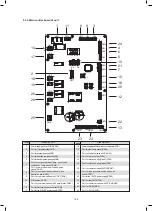
30
29
32
25
26
27
28
31
7
12
11
10
9
18
8
7
5
23
22
24
1
2
13
3
4
6
20
14
15
17
19
16
21
6
8
9
10
5
4
3
2
1
CN4
CN22
CN5
S3
DIS1
CN24
CN1
CN2
CN6
CN8
CN13
CN15
CN16
CN18
CN28
S2
CN42
CN21
S1
S4
CN11
CN7
CN17
CN19
CN30
CN35
CN14
CN31
CN36
CN25
CN29
CN40
CN41
CN32
SW9
123
122
Summary of Contents for MONO KHC-22RX3
Page 1: ...INSTRUKCJA INSTALACYJNA INSTALATIONMANUAL POMPA CIEPŁA MONO MONO TYPE HEAT PUMP PL EN ...
Page 2: ......
Page 79: ...79 ...
Page 80: ......
Page 157: ...NOTE 157 ...
Page 158: ...NOTE ...
Page 159: ...16125300002403 V C ...
Page 160: ...kaisai com ...

