45
* In addition to the LED display, the fault signal LED is continuously illuminated in red.
Code no.
Fault
Cause
Remedy
E04
Mains undervoltage
Power supply too low on mains
side
Check mains voltage.
E05
Power supply too high on
mains side
Mains overvoltage
Check mains voltage.
E09
Turbine operation
The pump is driven in reverse
(the fluid flows through the
pump from the pressure to the
suction side)
Check flow, install non-return
valves if necessary
E10
Blocking
Request customer service
Request customer service
Request customer service
Request customer service
Request customer service
The rotor is blocked
E21
*
Overload
Sluggish motor
E23
Short-circuit
Motor current too high
E25
Contacting/winding
Motor winding defective
E30
Module overheated
Module interior too warm
Improve room ventilation, check
operating conditions, request
customer service, if necessary
Improve room ventilation, check
operating conditions, request
customer service, if necessary
E31
Overheated power
section
Ambient temperature too high
E36
Electronic faults
Electronics defective
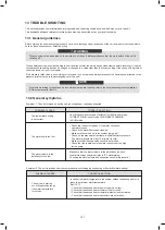
• The warning signal is indicated by the LED display.
• The fault signal LED and the SSM relay do not respond.
• The pump continues to run with limited output.
• The indicated faulty operating status must not occur for a prolonged period. The cause must be eliminated.
If the operating fault cannot be remedied, please consult a specialist technician or the nearest customer service
location or representative.
In order to ensure the service life of the pump, it is recommended that the unit run at least once every 2 weeks
(ensure that the pump is running) or keep it powered on for a long time (in the power-on standby state, the unit will
run the pump for 3 minutes every 6 hours)
NOTE
* See also fault signal E21
.
Code no.
Fault
Cause
Remedy
E07
Generator operation
Pump hydraulics have fluid
running through them.
Check the system
E11
Dry running
Air in the pump
Check the water volume/
pressure
E21
*
Overload
Sluggish motor, pump is oper-
ated outside of its specifica-
tions (e.g. high module
temperature). The speed is
lower than during normal
operation.
Check the ambient conditions
2) Warning signals
46
The unit shall be configured by the installer to match the installation environment (outdoor climate, installed options, etc.) and
user demand. A number of field settings are available. These settings are accessible and programmable through “FOR
SERVICEMAN” in user interface.
10.7 Field settings
When power on the unit, "1%~99%" is displayed on the user interface during initialization. During this process the user interface
cannot be operated.
Powering on the unit
Procedure
To change one or more field settings, proceed as follows.
Temperature values displayed on the wired controller (user interface) are in °C.
Keys
Function
MENU
• Go to the menu structure(on the home page)
BACK
• Come back to the up level
◄►
▼▲ • Navigate the cursor on the display
• Navigate in the menu structure
• Adjust settings
ON/OFF
• Turn on/off the space heating/cooling operation or DHW
mode
• Turn on/or off functions in the menu structure
UNLOCK
• Long press for unlock /lock the controller
• Unlock /lock some functions such as "DHW temperature
adjusting"
OK
• Go to the next step when programming a schedule in the
menu structure; and confirm a selection to enter in the
submenu of the menu structure.
NOTE
Press
▼
▲
to navigate and press
▼
▲
to adjust the
numerical value. Press OK. The password is 234, the
following pages will be displayed after putting the
password:
About FOR SERVICEMAN
"FOR SERVICEMAN" is designed for the installer to set
the parameters.
How to go to FOR SERVICEMAN
Go to MENU> FOR SERVICEMAN. Press OK:
Setting the composition of equipment.
Setting the parameters.
Please input the password:
ADJUST
OK
ENTER
0
0 0
FOR SERVICEMAN
OK
ENTER
FOR SERVICEMAN
1. DHW MODE SETTING
2. COOL MODE SETTING
3. HEAT MODE SETTING
4. AUTO MODE SETTING
5. TEMP.TYPE SETTING
6. ROOM THERMOSTAT
1/3
Press ▼ ▲ to scroll and use "OK" to enter submenu.
OK
ENTER
FOR SERVICEMAN
3/3
7. OTHER HEATING SOURCE
8. HOLIDAY AWAY MODE SET
TING
9. SERVICE CALL SETTING
10. RESTORE FACTORY SETTINGS
11. TEST RUN
12. SPECIAL FUNCTION
OK
ENTER
FOR SERVICEMAN
2/3
13. AUTO RESTART
14. POWER INPUT LIMITATION
15. INPUT DEFINE
16. CASCADE SET
17. HMI ADDRESS SET
129
128
Summary of Contents for MONO KHC-22RX3
Page 1: ...INSTRUKCJA INSTALACYJNA INSTALATIONMANUAL POMPA CIEPŁA MONO MONO TYPE HEAT PUMP PL EN ...
Page 2: ......
Page 79: ...79 ...
Page 80: ......
Page 157: ...NOTE 157 ...
Page 158: ...NOTE ...
Page 159: ...16125300002403 V C ...
Page 160: ...kaisai com ...


