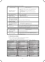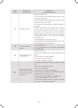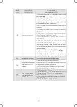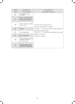
63
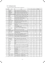
ERROR
CODE
MALFUNCTION
OR PROTECTION
FAILURE CAUSE
AND CORRECTIVE ACTION
The balance tank low
temp.sensor(Tbt2) fault
1.Check the resistance of the sensor.
2.The Tbt12 sensor connector is loosen,reconnect it.
3.The Tbt2 sensor connector is wet or there is water in,remove
the water ,make the connector dry.Add waterproof adhesive.
4.The Tbt2 sensor failure,change a new sensor.
The plate exchanger water inlet
temp. sensor (Tw_in) fault.
1.Check the resistance of the sensor.
2. The Tw_in sensor connector is loosen. Reconnect it.
3.The Tw_in sensor connector is wet or there is water in.
remove the water, make the connector dry. Add waterproof adhesive
4. The Tw_in sensor failure, change a new sensor.
The main control board of
hydraulic module EEPROM
fault.
1. The EEprom parameter is error, rewrite the EEprom data.
2. EEprom chip part is broken, change a new EEprom chip part.
3. main control board of hydraulic module is broken, change a new
PCB.
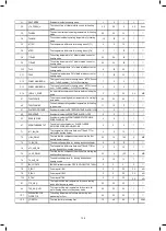
PED PCB fault
1. After 5 minutes of power-off interval, power on again and
observe whether it can be recovered;
2. If it can't be restored, replace PED safety plate, power
on again, and observe whether it can be restored;
3. If it can not be recovered, the IPM module board should
be replaced.
High temp. protection of
inverter module
1. Power supply voltage of the unit is low, increase the power
voltage to the required range.
2. The space between the units is too narrow for heat
exchange. Increase the space between the units.
3. Heat exchanger is dirty or something is block on the surface.
Clean the heat exchanger or remove the obstruction.
4. Fan is not running. Fan motor or fan is broken, Change a
new fan or fan motor.
5. Water flow rate is low, there is air in system, or pump head
is not enough. Release the air and reselect the pump.
6. Water outlet temp.sensor is loosen or broken, reconnect it or
change a new one.
DC bus low voltage protection
1. Check the power supply.
2. If the power supply is OK,and check if LED light is OK, check the
voltage PN, if it is 380V, the problem usually comes from the main
board. And if the light is OFF, disconnect the power, check the IGBT,
check those dioxides, if the voltage is not correct, the inverter board
is damaged, change it.
3. And if those IGBT are OK, which means the inverter board is OK,
power form rectifier bridge is not correct, check the bridge. (Same
method as IGBT, disconnect the power, check those dioxides are
damaged or not).
4. Usually if F1 exist when compressor start, the possible reason is
main board. If F1 exist when fan start, it may be because of inverter
board.
temp.sensor(T2B) fault
64
ERROR
CODE
MALFUNCTION
OR PROTECTION
FAILURE CAUSE
AND CORRECTIVE ACTION
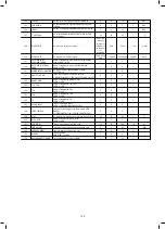
Communication fault between
main control board of hydraulic
module and main control board
PCB B.
1.wire doesn’t connect between main control board PCB B and main
control board of indoor unit. connect the wire.
2. Whether there is a high magnetic field or high power interfere, such
as lifts, large power transformers, etc.. To add a barrier to protect the
unit or to move the unit to the other place.
Communication fault between
inverter module PCB A and
main control board PCB B.
1. Whether there is power connected to the PCB and driven
board. Check the inverter module PCB indicator light is on or off. If
Light is off, reconnect the power supply wire.
2.if light is on, check the wire connection between inverter module
PCB and main control board PCB, if the wire loosen or broken,
reconnect the wire or change a new wire.
3. Replace a new main PCB and driven board in turn.
The plate exchanger refrigerant
outlet (liquid pipe) temp. sensor
(T2) fault.
The plate exchanger refrigerant
outlet (liquid pipe) temp. sensor
(T2) fault.
1.Check the resistance of the sensor
2.The T2 sensor connector is loosen. Re connect it.
3.The T2 sensor connector is wet or there is water in. remove the
water, make the connector dry. Add waterproof adhesive
4. The T2 sensor failure, change a new sensor.
The plate exchanger refrigerant
outlet (gas pipe) temp. sensor
(T2B) fault.
temp.sensor(T2B) fault
1.Check the resistance of the sensor
2. The T2B sensor connector is loosen. Reconnect it.
3.The T2B sensor connector is wet or there is water in. remove the
water, make the connector dry. Add waterproof adhesive
4. The T2B sensor failure, change a new sensor.
Three times P6 protection
Same to P6
Room temp.sensor (Ta) fault
1.Check the resistance of the sensor
2. The Ta senor is in the interface;
3. The Ta sensor failure
,
change a new sensor or change a new
interface, or reset the Ta, connect a new Ta from the indoor unit PCB
DC fan motor fault.
1. Strong wind or typhoon below toward to the fan, to make the fan
running in the opposite direction. Change the unit direction or make
shelter to avoid typhoon below to the fan.
2.fan motor is broken, change a new fan motor.
Main circuit voltage protection
fault.
1. Whether the power supply input is in the available range.
2. Power off and power on for several times rapidly in short time.
Remain the unit power off for more than
3 minutes than power on.
4. the circuit defect part of Main control board is defective. Replace a
new Main PCB.
Pressure sensor fault.
1. Pressure sensor connector is loosen, reconnect it.
2. Pressure sensor failure. change a new sensor.
147
146
Summary of Contents for MONO KHC-22RX3
Page 1: ...INSTRUKCJA INSTALACYJNA INSTALATIONMANUAL POMPA CIEPŁA MONO MONO TYPE HEAT PUMP PL EN ...
Page 2: ......
Page 79: ...79 ...
Page 80: ......
Page 157: ...NOTE 157 ...
Page 158: ...NOTE ...
Page 159: ...16125300002403 V C ...
Page 160: ...kaisai com ...

