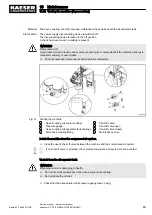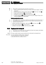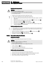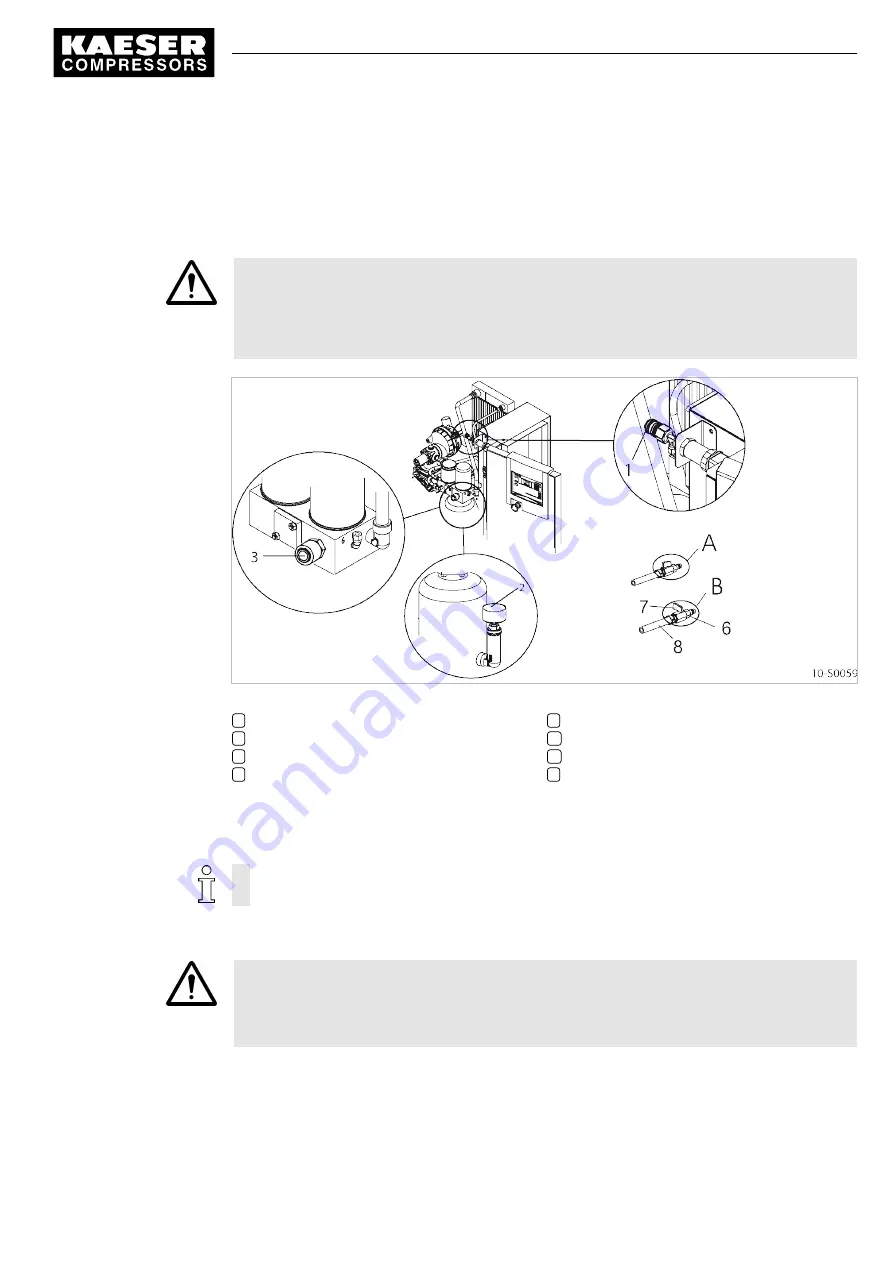
Material The hose coupling, shut-off valve and maintenance hose lie beneath the oil separator tank.
Precondition The power supply disconnecting device is switched off
The disconnecting device is locked in the off position
A check has been made no voltage is present
WARNING
Compressed air!
Compressed air and devices under pressure can injure or cause death if the contained energy is
released suddenly or uncontrolled.
➤ Vent all pressurized components and chambers completely.
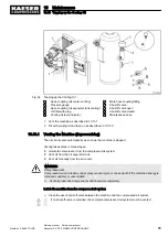
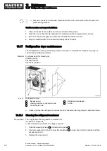
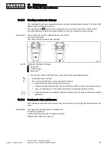
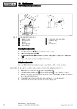
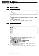
Fig. 31 Venting the machine
1
Hose coupling (air cooler venting)
2
Pressure gauge
3
Hose coupling (oil separator tank venting)
6
Male hose coupling/fitting
7
Shut-off valve.
A
Shut-off valve open
B
Shut-off valve closed
8
Maintenance hose
Isolate the machine from the compressed air system.
➤ Close the user's shut-off valve between the machine and the compressed air system.
If no shut-off valve is provided, the complete compressed air system must be vented.
Vent air from the oil separator tank.
WARNING
Escaping oil mist is damaging to health.
➤ Do not direct the maintenance hose at a person while venting.
➤ Do not inhale the oil mist.
➤ Check that the oil separator tank pressure gauge reads 0 psig.
10 Maintenance
10.12 Venting the machine (depressurizing)
Number: 9_6945 01USE
Service manual Screw compressor
Aircenter SX 3/7.5 SIGMA CONTROL BASIC
63

